
Author: Nathan Zenero, OXBO Energy, LLC · Contributing review: David M. Baker, PG (Licensed Professional Geologist)
Audience. This module is written for working geoexchange and water-well drillers and their field crews. It is equally intended for the contractors, design engineers, specifiers, and regulatory authorities who share legal and operational responsibility for the subsurface bores they construct.
Well control is pressure control
Well control is fundamentally the management of subsurface fluid pressure. Because fluid flow cannot occur without a driving pressure differential, identifying and understanding the origin of pressure is the indispensable foundation for all well control practice.
Pressure cannot be controlled until it is recognized, and it cannot be recognized until its physical origin is understood. Any subsurface pressure encountered at the wellbore arrives through a systematic three-stage progression: it is created by a distinct physical mechanism, stored behind a geological seal, and accessed along a hydraulic pathway—most often the wellbore itself. Creation, storage, and access represent the three core stages that structure the analysis in this module. A pressure mechanism that was never initiated cannot be stored; a pressure that was created but lacks a seal dissipates naturally into the surrounding formations; and a pressure that is created and stored but never intersected presents no operational hazard. The drilling crew encounters only pressure that has completed all three stages.
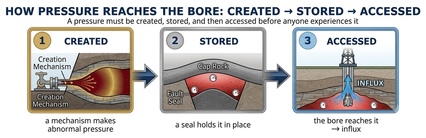
This three-stage framework applies equally to fluid pressures of either sign relative to the borehole:
- Source Zones: A formation may retain a surplus of pressure relative to the wellbore fluid, driving an influx into the borehole upon intersection.
- Sink Zones: A formation may exhibit a pressure deficit, absorbing borehole fluids and resulting in lost circulation.
This module systematically addresses both operational extremes.
The scope of this module is restricted to pressures that can be identified prior to spudding. These fall into two primary categories: naturally occurring geological mechanisms and pre-existing anthropogenic activities. Both categories can be comprehensively evaluated through a thorough pre-drilling desk study. Conversely, operational pressures dynamically induced by the drilling process itself—such as surge, swab, and circulation friction—cannot be forecasted by historical desk studies and must instead be managed through sound operational practice. These dynamically induced pressures form the subject of Module 2.
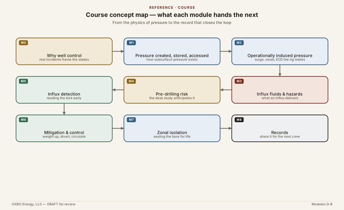
The subsequent modules in this series build directly upon these foundational concepts:
- Module 2: Examines operationally induced pressure dynamics (including surge, swab, ground-loop insertion hydrostatic impacts, and chemical, mechanical, or thermal modification of the formation) and provides mitigation protocols.
- Module 3: Analyzes the physical properties of formation fluids delivered by differential pressure and evaluates their specific risks to health, safety, property, and the environment.
- Module 4: Establishes pre-drilling methodologies for assessing and quantifying regional influx risks.
- Module 5: Details real-time methods for detecting pressure anomalies and impending influxes while drilling.
- Module 6: Covers the selection and deployment of primary and secondary well control barriers, utilizing source characteristics to anticipate pressure magnitude and duration.
- Module 7: Focuses on the long-term structural and hydraulic integrity of grouting materials required to withstand differential formation pressures across the entire operational lifespan of the asset.
- Module 8: Outlines standardized post-drilling reporting practices to ensure subsurface data and encountered hazards are accurately transferred to future operators.
To assist the practitioner in anticipating hazards, each mechanism discussed in this module is analyzed through three operational criteria: the underlying physical process, its specific manifestation at the drill rig, and the archival data sources that should predict its occurrence.
A Note on Shared Responsibility
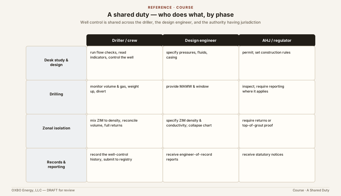
The legal and operational duty to maintain well control is a shared obligation distributed among three principal entities: the regulatory authority issuing the permit, the professional engineer designing the borefield, and the driller operating the rig. Each party holds an essential component of a single, unified duty: to identify subsurface pressure before it is intersected. These responsibilities are distinct, non-interchangeable, and mutually dependent.
The primary burden of predictive geological analysis rests with the design engineers and the authority having jurisdiction. These parties possess the site maps, historical well records, and technical resources, as well as the requisite lead time to conduct detailed subsurface evaluations prior to permitting and construction. The driller’s primary responsibility lies in operational recognition and immediate response. The driller must recognize the physical signatures of pressure mechanisms from the rig floor, formulate critical field inquiries, and verify that predictive site evaluations have been completed. Historical incident records demonstrate a recurring failure mode: each entity erroneously assumes that another party has evaluated and mitigated the subsurface pressure risk. Well control safety requires that every participant execute their specific role within this shared framework.
Module Structure
- Section 1.1 Establishes the foundational physical definitions and units of pressure.
- Section 1.2 Defines normal hydrostatic equilibrium and quantifies departures into abnormal and subnormal regimes.
- Sections 1.3, 1.4, and 1.5 Systematically examine the progression of pressure creation, storage, and access.
- Section 1.6 Synthesizes these principles, applying them directly to pre-drilling desk studies and permanent zonal isolation strategies.
1.1 Physical Definitions and Operational Expressions of Pressure
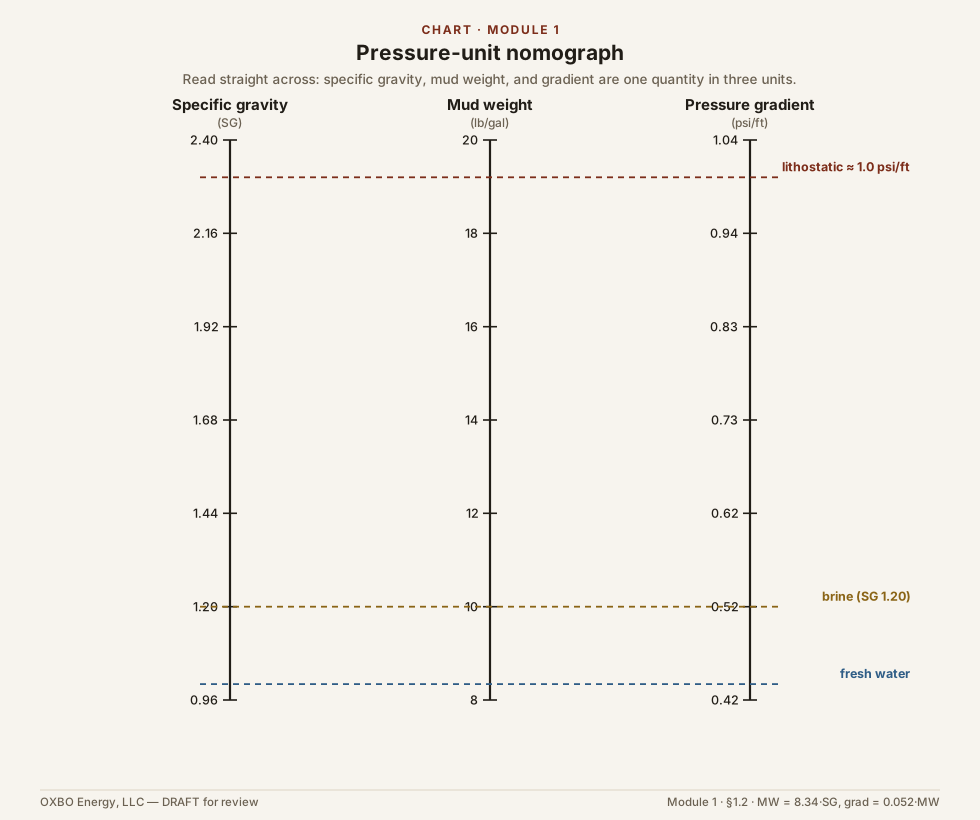
The term pressure carries distinct technical interpretations across engineering and scientific disciplines. Operational errors in well control frequently arise from misunderstandings when cross-disciplinary teams use the term without a shared baseline:
- To the design engineer, pressure is mechanical force distributed over a unit area, governing hydraulic system performance and structural material limits.
- To the geologist, pressure is evaluated as a vertical gradient relative to depth and lithology, used to differentiate normal hydrostatic conditions from overpressured rock units.
- To the physicist, pressure represents thermal and mechanical energy stored per unit volume of fluid.
- To the driller, pressure is an operational differential—the margin between the hydrostatic column of the fluid inside the wellbore and the pore pressure of the surrounding formation—which dictates whether the well remains static or begins to flow.
Effective well control practice requires unifying these perspectives. The following subsections analyze pressure as force, energy, and gradient, culminating in the standardized operational expressions used on the rig floor.
Pressure as Force per Unit Area
The classical definition of pressure as force per unit area () governs mechanical equipment ratings, pump discharge dynamics, and the burst and collapse thresholds of casing and loop materials. While straightforward in closed hydraulic systems, this definition must be expanded when applied to complex, multi-phase fluids within a borehole.
Pressure as Energy per Unit Volume
Formation fluids are rarely pure or homogeneous; they frequently consist of complex mixtures of water, dissolved minerals, polymers, emulsions, and dissolved gases. Subsurface fluid pressure can be masked by gas dissolved in solution or by phase transitions driven by pressure, volume, and temperature (PVT) changes.
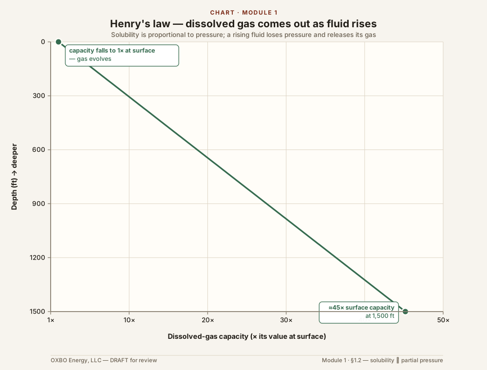
The concentration of gas dissolved in a formation fluid follows Henry’s Law, which states that the solubility of a gas in a liquid is directly proportional to the partial pressure of that gas above the liquid. As confining pressure decreases during fluid extraction or circulation up the borehole, gas comes out of solution. Once a gas phase evolves, the total pressure exerted by the gas mixture equals the sum of the partial pressures of its individual components (Dalton’s Law).
In dimensional analysis, pressure is equivalent to energy density (). Advanced well control modeling utilizes this energy-density formulation to maintain thermodynamic consistency when converting between mechanical work, hydrostatic head, and gas expansion during phase changes.
Pressure as a Vertical Gradient
In field operations, formation pressure is primarily expressed as a pressure gradient—the change in pressure per unit of vertical depth (expressed in or ). Expressing pressure as a gradient serves three vital operational functions:
- It provides an immediate benchmark for identifying subnormal or abnormal formation pressures across varying lithological units.
- It simplifies hydrostatic pressure calculations at any target depth into basic linear arithmetic.
- It enables direct comparison with critical operational thresholds, most notably the formation fracture gradient, which establishes the maximum allowable fluid density to prevent induced hydraulic fracturing.
A normally pressured formation exists in hydraulic equilibrium with its regional hydrogeologic environment. Over geological time, compaction forces pore fluids into hydraulic communication with the surface. Under normal conditions, the pore fluid pressure at any true vertical depth (TVD) equals the hydrostatic weight of a continuous fluid column extending to the water table. For a composite column comprising distinct fluid intervals, the hydrostatic pressure is calculated as:
where is the specific gravity of the -th fluid relative to pure water, is the vertical interval of that fluid in feet, and is the hydrostatic pressure gradient of pure water ().
In oilfield and deep drilling operations, this relationship is conventionally expressed using mud weight density (, in pounds per gallon):
This form is mathematically equivalent, as , and the conversion factor satisfies .
Equivalent Mud Weight (EMW)
The second fundamental operational metric is Equivalent Mud Weight (EMW), which converts a measured formation pressure at depth into the equivalent fluid density required to balance that pressure hydrostatically:
EMW allows the rig crew to evaluate formation pressures directly in terms of fluid density requirements. Whether evaluating a bottomhole pressure or assessing a potential influx zone, expressing pressure as EMW ensures that drillers, engineers, and geologists share a common operational baseline.
1.2 Hydrostatic Baseline and Deviations: Overpressure and Subpressure
A formation is defined as normally pressured when its internal pore pressure exactly equals the hydrostatic pressure exerted by a column of formation water extending from that depth to the regional water table. Normal pressure does not represent an unyielding static constant; rather, it reflects a state of dynamic equilibrium achieved when pore fluids maintain hydraulic continuity with the surface over geological time. Given sufficient permeability and time, excess pore pressures bleed off until hydrostatic balance is re-established.
Any departure from this baseline represents an operational hazard:
- Abnormal Pressure (Overpressure): Occurs when formation pore pressure exceeds the regional hydrostatic baseline. An overpressured formation functions as a fluid source, capable of driving an influx (kick) into the wellbore if the borehole fluid column is insufficient.
- Subnormal Pressure (Underpressure): Occurs when formation pore pressure is less than the regional hydrostatic baseline. A subnormally pressured formation acts as a fluid sink, absorbing borehole fluids and causing lost circulation.
Lost circulation into a sink zone reduces the vertical height of the borehole fluid column, decreasing hydrostatic pressure throughout the wellbore. This hydrostatic reduction frequently triggers a secondary influx from an overpressured source zone intersected elsewhere in the same hole.
Baseline Calculation Example
To illustrate the baseline mathematical relationships, consider a formation situated at a True Vertical Depth of ().
Normal Hydrostatic Pressure (Freshwater Baseline):
Overpressured Condition: If a shut-in casing gauge indicates a static formation pressure of at , the zone exhibits an abnormal overpressure excess of above hydrostatic balance. A standard column of fresh water () cannot contain this pressure. The required Equivalent Mud Weight to balance the zone is:
Subpressured Condition: If the same formation exhibits a static pore pressure of , it carries a subnormal deficit of . A full wellbore column of fresh water will flow into the formation until the fluid column drops to a height of (), at which point hydrostatic equilibrium is restored.
1.3 Pressure Creation: Mechanisms of Generation
Deviations from normal hydrostatic pressure require specific physical or chemical mechanisms of creation. This section details the primary geological processes and pre-existing human activities that generate abnormal source pressures and subnormal sink conditions prior to drilling.
Compaction Disequilibrium (Undercompaction)
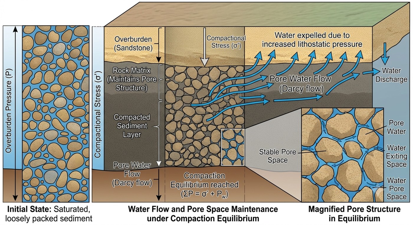
As fine-grained sediments such as clays and muds accumulate in marine or lacustrine environments, their initial porosity often exceeds 50%. Under normal burial rates, increasing overburden load compresses the sediment matrix, expelling interstitial water through connected pore networks. So long as pore water escapes at a rate equal to the loading rate, pore pressure remains hydrostatic, and the weight of the overlying rock matrix is supported entirely by grain-to-grain contact stress.
However, when fine-grained, low-permeability sediments are buried rapidly, pore water cannot escape fast enough to accommodate the structural compaction. Trapped within the pore space, the incompressible fluid is forced to carry a significant portion of the overburden load. As burial continues, the fluid pressure increases above normal hydrostatic levels, a condition known as compaction disequilibrium or undercompaction.
Compaction disequilibrium is predominantly a deep sedimentary basin phenomenon (e.g., the Gulf Coast basin or young deltaic deposits) (Dickinson, 1953; Osborne and Swarbrick, 1997). While shallow geoexchange bores in consolidated bedrock or thin glacial drift rarely encounter compaction disequilibrium, bores drilled into thick, rapidly deposited Cenozoic sedimentary sequences may intersect undercompacted zones at shallow depths.
Gas Generation: Thermogenic vs. Biogenic
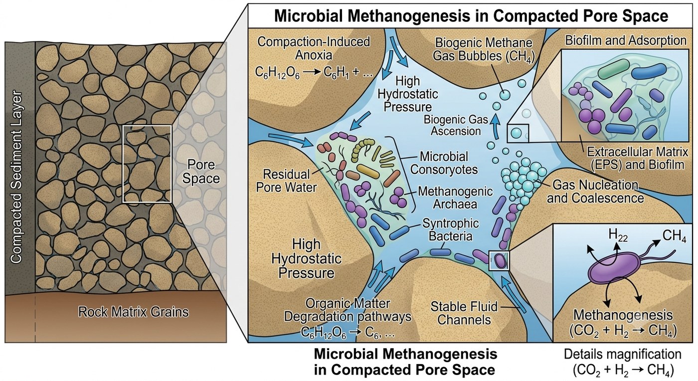
The generation of hydrocarbons within closed pore spaces increases fluid volume, raising pore pressure if the surrounding rock acts as a seal. In geoexchange drilling, distinguishing between thermogenic and biogenic gas is critical:
- Thermogenic Gas: Formed by the thermal cracking of organic matter at deep subsurface depths () under high temperatures over geological time. Where thermogenic gas occurs at shallow depths, it has migrated vertically along faults and fractures, been uplifted toward the surface, or been encountered where it migrated through a compromised wellbore.
- Biogenic Gas: Produced at shallow depths and low temperatures () by anaerobic microbial decomposition of organic matter in post-glacial, lacustrine, or estuarine sediments.
Biogenic gas generation is widespread at typical geoexchange drilling depths () (Rice and Claypool, 1981). Organically rich strata—such as buried peat beds, glacial valley fills, and shallow dark shales—frequently generate localized biogenic gas pressures. Because these shallow deposits are rarely identified on commercial petroleum maps, they represent subtle operational hazards.
Thermal and Fluid Expansion
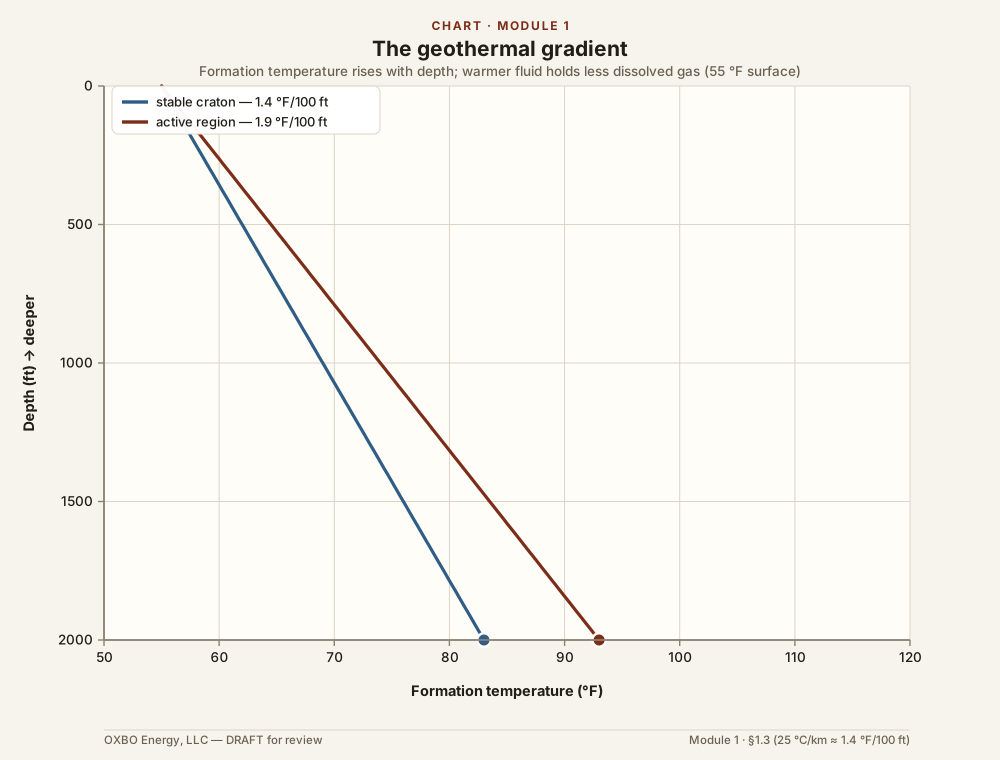
Subsurface temperatures increase along the geothermal gradient, averaging () in stable continental cratons and exceeding () in tectonically active regions. Geothermal heating influences formation pressure through three primary mechanisms:
- Volumetric Expansion: Heating expands pore fluids. In low-permeability, sealed formations, constrained fluid expansion elevates pore pressure.
- Density Reduction: Thermal expansion decreases fluid density, reducing the total hydrostatic weight exerted by a hot vertical fluid column relative to a cooler standard column.
- Gas Desorption and Phase Separation: Higher fluid temperatures decrease the solubility of dissolved gases in formation water, causing free gas bubbles to evolve as fluid ascends toward lower-pressure environments.
Uplift, Erosional Unloading, and Thermal Cooling
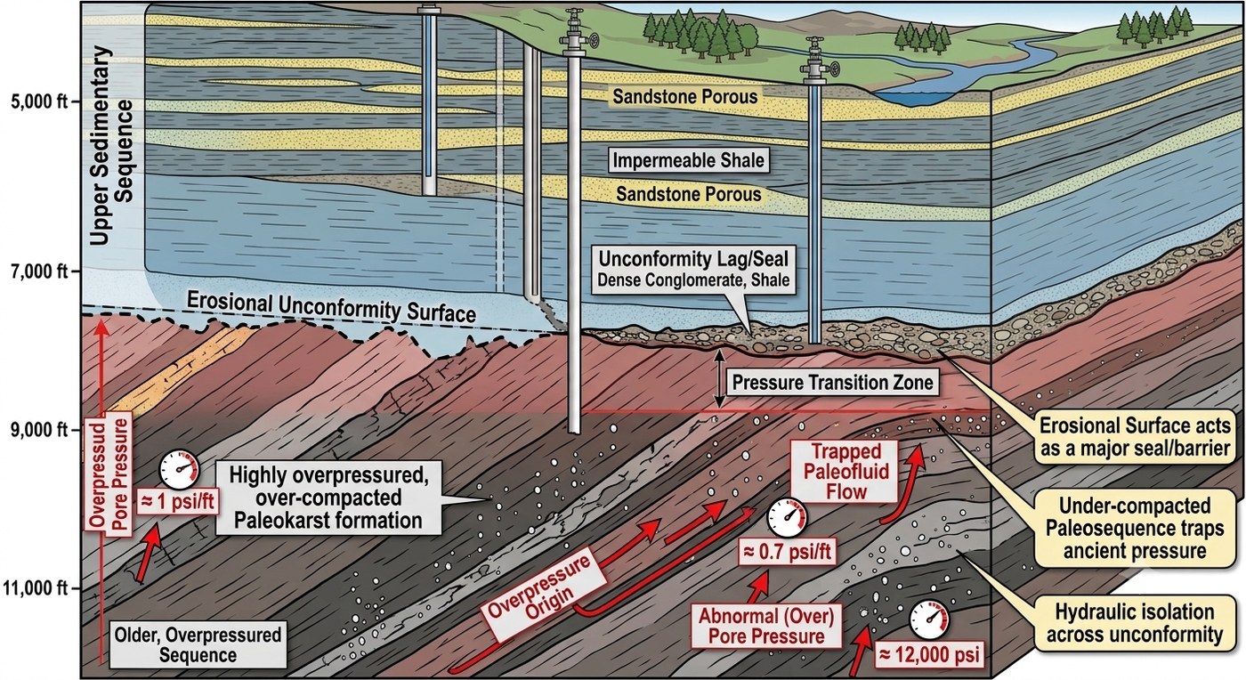
Geological uplift and subsequent erosion alter formation pressure profiles, creating overpressured sources or subpressured sinks depending on local rock properties:
- Inherited Overpressure: A sealed formation that reaches hydraulic equilibrium at depth retains its original pore pressure if rapidly uplifted toward the surface. When intersected near the surface, the formation retains the pore pressure characteristic of its previous burial depth, displaying significant overpressure relative to its new shallow baseline.
- Inherited Subpressure (Unloading Sink): When dense, low-permeability rocks are uplifted and overburden is removed by erosion, the rock matrix undergoes elastic relaxation and pore volume expansion. If low permeability prevents groundwater from infilling the expanded pore space, internal pore pressure drops below hydrostatic levels, creating a subpressured sink (Neuzil and Pollock, 1983; Birchall et al., 2022). Subsequent cooling of the formation fluid further reduces pore pressure.
Tectonic Compression and Seismic Loading
In active tectonic settings, lateral compressive stresses subject water-saturated formations to horizontal loading, increasing pore fluid pressure in a process analogous to rapid vertical burial.
In regions such as the California Coast Ranges, lateral tectonic compression creates pore pressures that approach the full weight of the lithostatic overburden. Furthermore, transient seismic waves passing through saturated formations produce rapid compression-relaxation cycles that generate momentary pore pressure spikes, occasionally resulting in temporary groundwater artesian surges or localized liquefaction.
The Lithostatic Limit (Overburden Gradient)
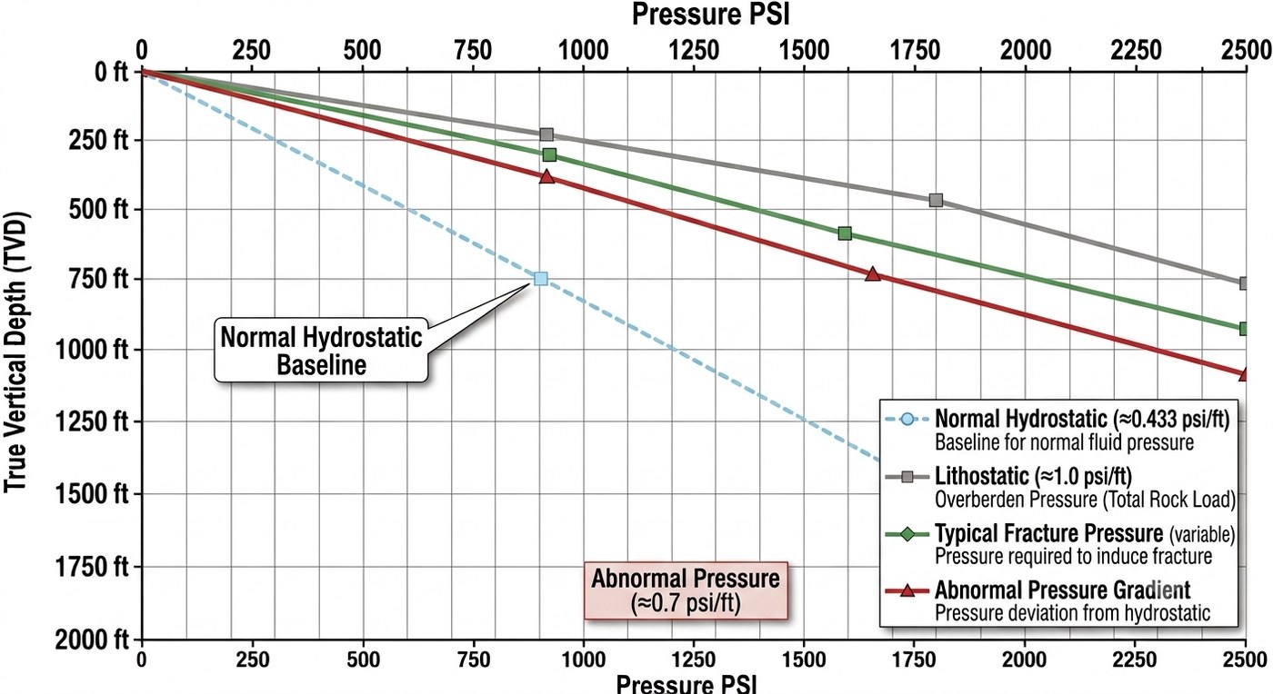
When compaction disequilibrium or extreme tectonic stress causes pore fluid pressure to equal the total weight of the overlying rock mass, the fluid reaches the lithostatic limit.
Under normal hydrostatic conditions, the solid rock framework carries the rock overburden, while the pore fluid carries only its own hydrostatic weight. If the structural framework fails or fails to consolidate, the pore fluid must support the entire overburden weight. The lithostatic pressure gradient averages approximately ( or an EMW of ), compared to the freshwater hydrostatic gradient of ().
Intersects with near-lithostatic formations present severe well control challenges that cannot be managed using standard, unweighted geoexchange drilling fluids. Predicting these zones via pre-drilling desk studies is essential for establishing safe casing and mud weight specifications.
Elevated Recharge and Artesian Pressure
The most common cause of high pressure encountered in geoexchange drilling is elevated artesian recharge. Artesian conditions occur when a permeable aquifer is confined beneath an impermeable aquitard and extends laterally to a recharge zone located at a higher elevation.
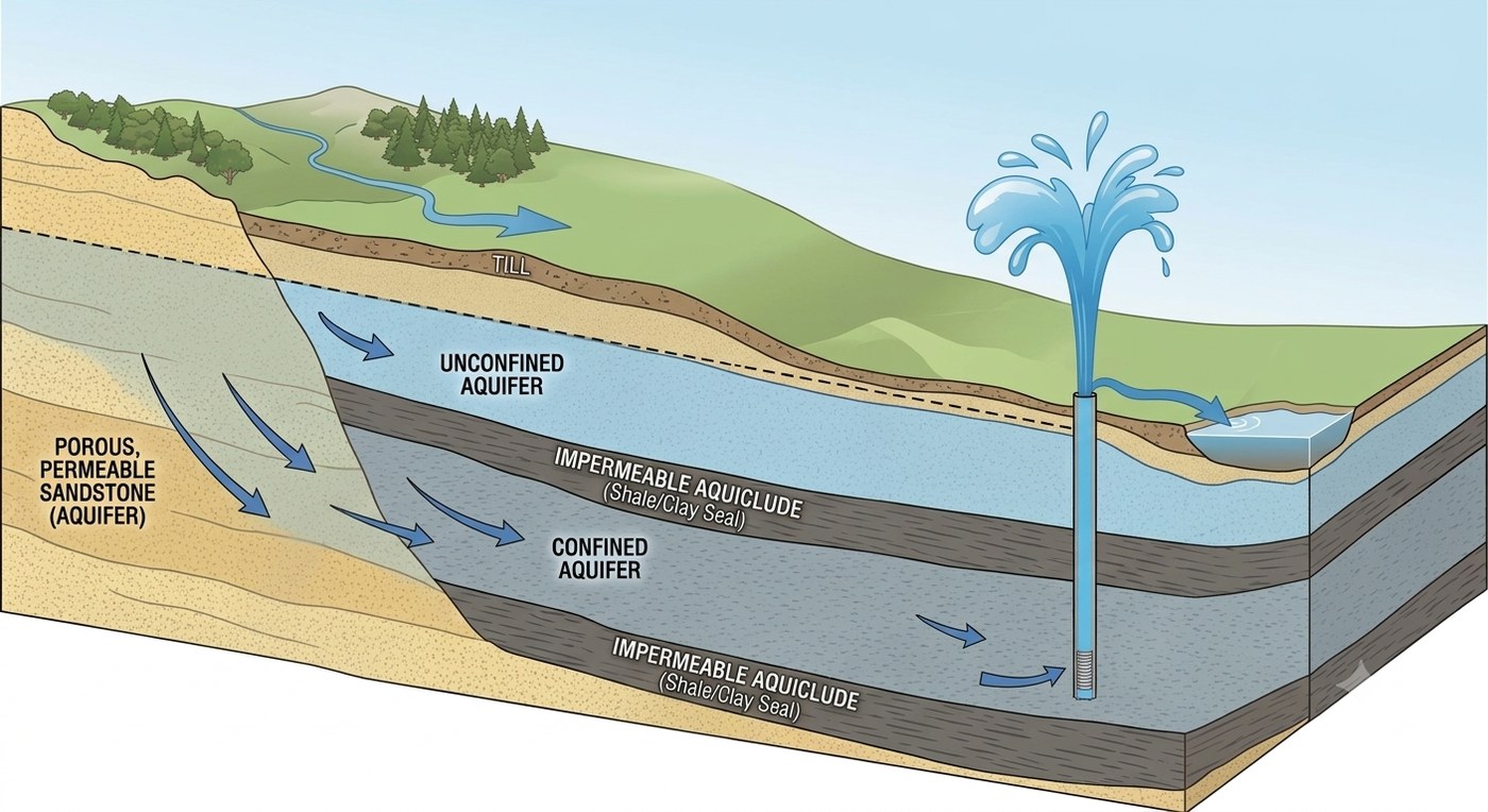
The hydraulic head established by the elevated recharge area projects a potentiometric surface across the confined aquifer (Heath, 1983). If the ground elevation at the drilling rig sits below this potentiometric surface, the formation fluid carries an elevated static pressure. Upon penetrating the upper confining layer, water rises naturally toward the potentiometric surface.
To compute the static pressure of an artesian aquifer situated at a depth of () below ground level, whose potentiometric surface sits () above ground level:
The operational pressure gradient referenced to the surface casing collar is:
If drilled with unweighted fresh water (), the well will flow uncontrollably. Shutting in the well at the surface yields a surface casing pressure reading corresponding only to the hydraulic head above ground surface:
A small surface pressure reading can conceal an aquifer capable of high sustained flow rates, creating severe surface flooding and erosion if breached without proper fluid weight or blowout preventers.
Pre-existing Anthropogenic Sources and Sinks
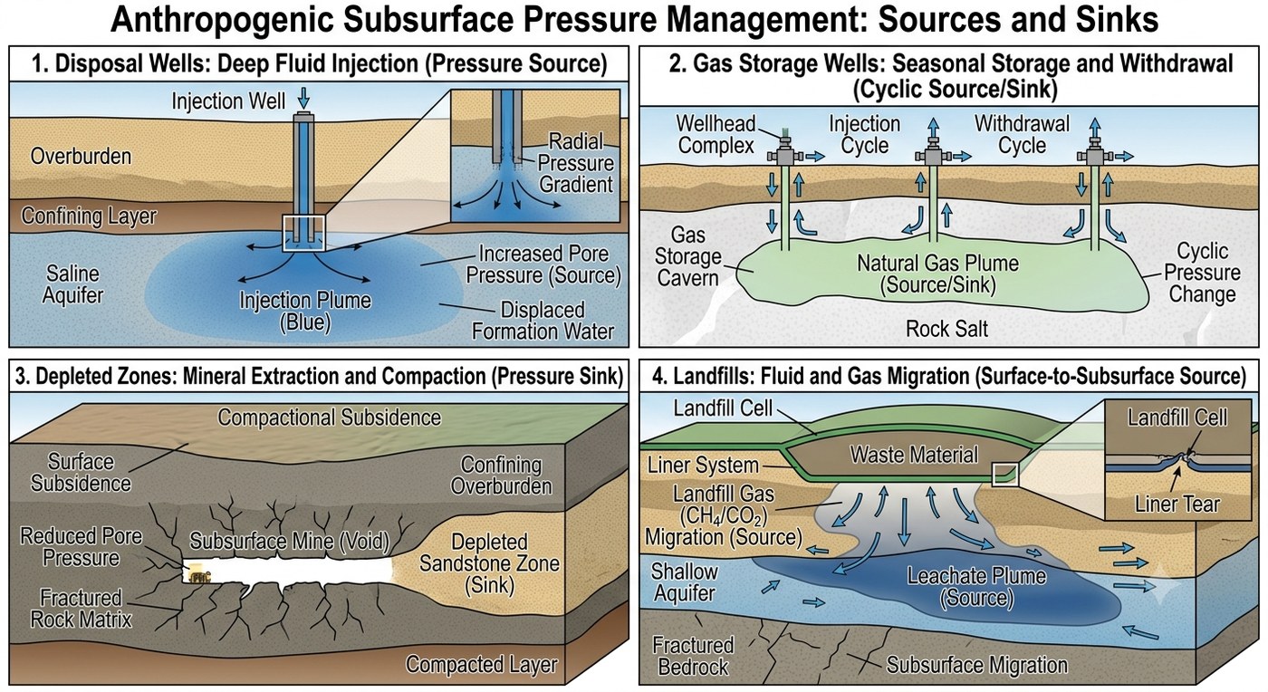
Human activities frequently create artificial pressure anomalies or subterranean sinks that must be identified prior to site operations:
- Fluid Injection and EOR: Deep well injection of industrial wastewater, carbon dioxide, or secondary oil recovery fluids elevates localized formation pressures miles from the injection wellhead.
- Underground Gas Storage (UGS): Depleted natural gas reservoirs or salt caverns converted for seasonal gas storage are cyclically pressurized to high operating pressures. Compromised legacy infrastructure in these fields poses severe shallow gas migration risks.
- Regional Groundwater Extraction: Long-term municipal or agricultural pumping lowers water tables and depressurizes aquifers, creating subnormal sink zones (Konikow, 2013). Subsequent cessation of pumping or active artificial recharge can rapidly restore or elevate regional pressures.
- Depleted Hydrocarbon Formations: Depleted oil and gas sands display subnormal pressures, acting as severe thief zones that induce fluid loss.
- Abandoned Underground Mine Workings: Flooded or open mine voids create immediate lost-circulation risks or carry unexpected hydraulic heads. Furthermore, mine voids may contain toxic or flammable gases (methane, carbon monoxide, hydrogen sulfide, and oxygen-depleted air) capable of migrating into shallow boreholes.
- Landfill Gas and Leachate: Unlined or historical municipal landfills generate landfill gas (predominantly methane and carbon dioxide) under positive pressure, alongside contaminated leachate under hydraulic head, which can migrate laterally through permeable surficial strata.
1.4 Pressure Storage: Sealing Mechanisms and Trapping Geometries
A created pressure anomaly cannot persist over geological time without an effective storage mechanism. Fluid pressure dissipates unless contained by low-permeability rock units (seals) configured in structural or stratigraphic geometries (traps). Storage describes how overpressure is retained within source zones and how volumetric capacity is maintained within sink zones.
Physical Sealing Mechanisms
A seal is a geological unit with permeability so low that fluid migration across it is negligible under ambient pressure differentials. Geological seals operate through two primary physical mechanisms:
- Capillary Seals: Fine-grained siliciclastic rocks (shales, mudstones, and clays) possess extremely small pore throat radii. The capillary entry pressure required to force a non-wetting fluid (such as gas or oil) through these narrow pore throats exceeds the buoyant driving pressure exerted by the trapped fluid.
- Crystalline/Cemented Seals: Evaporites (halite, anhydrite), highly cemented sedimentary rocks (siliciclastics and carbonates), and crystalline rocks possess near-zero interconnected porosity, forming impermeable physical barriers to all fluid phases.
The effectiveness of a seal is relative to the differential pressure applied across it. A shale unit that leaks under high pressure differentials in a deep basin may function as an absolute seal against the modest overpressures typical of shallow geoexchange depths.
Structural and Stratigraphic Traps
A trap consists of a seal geometry that prevents the upward or lateral migration of buoyant fluids. Trapped fluids segregate vertically by density, establishing equilibrium layers of gas over oil over water.
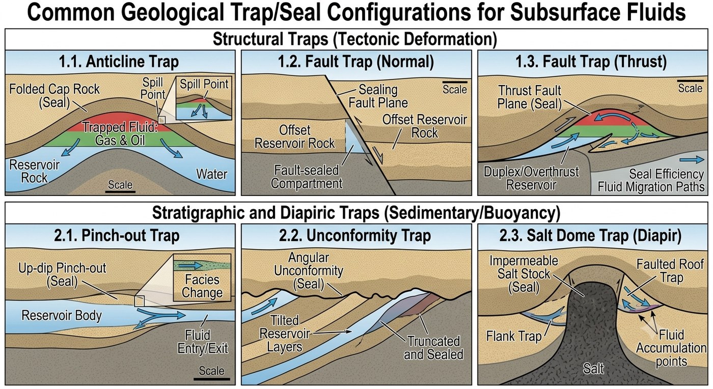
Common trap configurations include:
- Anticlines: Folded structural domes capped by impermeable strata.
- Fault Traps: Permeable strata truncated by impervious fault planes or juxtaposed against impermeable formations.
- Stratigraphic Pinches: Porous sedimentary lenses completely enclosed within low-permeability shales or clays.
When a drill bit penetrates a structural trap seal, the wellbore becomes an open hydraulic conduit, exposing the drilling fluid column to the full stored pressure of the reservoir.
Thinly Bedded Shale/Sand Sequences
In interbedded shale and sand sequences, every shale layer acts as a potential seal, and every sand functions as a potential pressure reservoir. Where shales contain organic matter, biogenic gas generated within the shale migrates directly into adjacent sand lenses. Consequently, drillers operating in interbedded sequence geology encounter multiple independent, stacked pressure compartments rather than a single predictable seal.
Evaporite Storage and Dissolution Voids
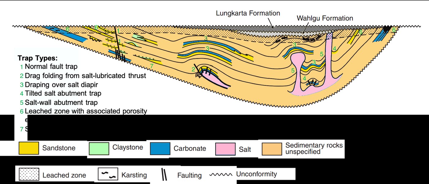
Salt (halite) forms an ideal crystalline seal with near-zero fluid permeability (Hudec and Jackson, 2007). Fluids sealed beneath salt bodies remain trapped indefinitely under high pressures. However, exposure to circulating fresh groundwater dissolves halite and gypsum, creating extensive sub-surface dissolution voids and collapse features. These voids act as severe lost-circulation sinks during drilling. Additionally, dissolution fluids form dense mineral brines (, gradient ), generating local overpressures relative to fresh water columns.
Gas Column Buoyancy Amplification
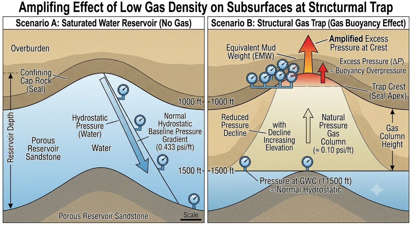
The low density of gas relative to water significantly amplifies fluid pressure at the crest of a structural trap. Because the hydrostatic gradient of natural gas () is far lower than that of fresh water (), pressure declines slowly with increasing elevation within a continuous gas column.
To quantify this buoyancy effect, consider a continuous gas column extending from a water-gas contact at () up to the seal crest at (), where the baseline water pressure at is normally pressured:
Pressure at Base of Gas Column ():
Pressure at Top of Gas Column ():
Normal Hydrostatic Baseline at :
Pressure Excess at Crest:
Although the formation pressure is completely normal at the base of the gas sand (), the density difference between the gas and surrounding water generates a overpressure at the structural crest (). Penetrating the crest of a tall gas column exposes the borehole to high initial gas pressures.
Shallow Glacial Drift Gas Storage
In glaciated regions, organic material buried beneath glacial till and outwash undergoes microbial decay, generating biogenic methane stored within localized sand and gravel lenses.
These shallow drift-gas deposits occur unpredictably within confined valley-fill deposits. While individual drift-gas pockets contain limited total gas volume, they emit high initial pressures upon intersection. In enclosed rig buildings or pump houses, released methane rapidly reaches its explosive range ( by volume in air), presenting severe ignition hazards.
1.5 Pressure Access: Pathways and Wellbore Intersection
Stored pressure remains isolated until a hydraulic pathway connects the high-pressure reservoir to a lower-pressure environment or the surface. Access occurs through natural geological conduits, legacy wellbores, or the primary drilling operation.
Faults and Fractures
Fault zones function as vertical or lateral hydraulic conduits that breach impermeable seals and connect isolated pressure regimes.
Extensional tectonic faulting creates grabens and horst blocks, placing contrasting lithologies and pressure regimes in direct contact across fault planes. Crossing a major fault plane while drilling can cause abrupt transitions in formation pressure, mud weight requirements, and lost-circulation risks.
Unconformities
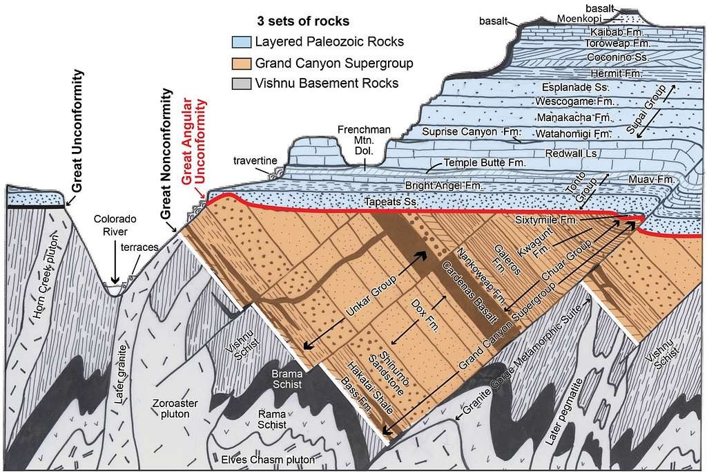
An unconformity represents a structural boundary where younger strata rest upon an eroded, older geological surface. Unconformities may act as operational pressure access pathways in two ways:
- Pressure Boundaries: They separate distinct hydrogeologic systems with different burial and compaction histories, causing rapid shifts in pore pressure gradients upon intersection.
- Permeable Migration Pathways: Weathered, highly permeable paleosols and basal conglomerates along unconformity surfaces carry pressurized fluids laterally over significant regional distances.
Subsurface Migration and Regional Interconnection
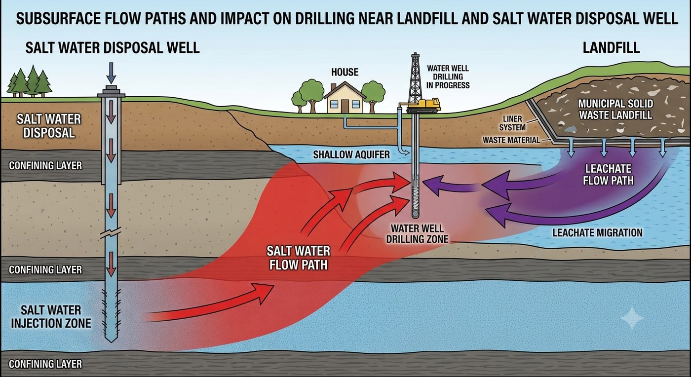
Pressurized gas and fluids migrate laterally along regional fractures, permeable carrier beds, and compromised wellbores, breaching original structural traps and charging shallow formations miles from their source.
- Hutchinson, Kansas (2001): High-pressure natural gas leaking from an underground storage facility migrated over seven miles laterally through a thin dolomite bed, erupting through abandoned brine wells in downtown Hutchinson, causing explosions and fatalities.
- Oakville, Ontario (2012): A shallow residential geothermal borehole intersected an unmapped gas-charged zone at a depth of , resulting in gas migration into nearby residential structures.
Buried Bedrock Valleys
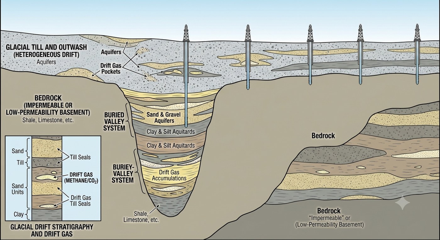
Pre-glacial river valleys carved into bedrock were subsequently filled with permeable sand, gravel, and overlying till during glacial events. These buried valleys represent complex drilling environments characterized by:
- High-yield artesian aquifers confined beneath impermeable clay till.
- Localized accumulations of shallow drift gas.
- Abrupt lateral variations in subsurface geology over short distances.
Because buried valley margins drop off sharply, offset well records located short distances away provide little assurance of subsurface conditions. Drilling within buried-valley terrain requires dedicated localized site investigations.
Legacy and Offset Wellbores
Unplugged or improperly abandoned legacy oil, gas, brine, and water wells form artificial vertical conduits through geological seals. Corroded casing strings or degraded cement sheaths allow pressurized deeper fluids to migrate vertically into shallow, freshwater aquifers (Kang et al., 2014). Intersecting an abandoned, unmapped wellbore or drilling into a shallow sand charged by legacy infrastructure introduces severe pressure and fluid influx hazards.
Chemically Reactive Formations
Certain mineral formations react chemically when accessed by water-based drilling fluids:
- Anhydrite (): Hydrates upon contact with fresh water to form gypsum (), resulting in a molar volume expansion of up to (Sass and Burbaum, 2010). Uncontrolled hydration exerts destructive swelling pressures against casing strings, wellbores, and adjacent structural foundations.
- Reactive Shales: Absorb water molecules, leading to severe swelling, bit balling, and total hole collapse.
While chemical reactions are initiated by borehole fluid contact, predicting reactive lithologies through pre-drilling desk studies is necessary to formulate non-reactive drilling fluid systems and proper casing designs.
1.6 Synthesis: The Desk Study, Shared Duty, and Zonal Isolation
The operational safety of a geoexchange drilling project depends upon systematically analyzing the three stages of pressure progression—creation, storage, and access—prior to site mobilization.
| Progression Stage | Geological/Anthropogenic Mechanisms | Operational Manifestation at Rig Floor | Primary Predictive Desk Study Sources |
|---|---|---|---|
| 1. Creation | Compaction disequilibrium, biogenic/thermogenic gas generation, thermal expansion, uplift, tectonic stress, elevated artesian recharge, anthropogenic injection/storage. | Uncontrolled fluid influx, elevated shut-in casing pressure, unexpected artesian surface flow, localized gas kick. | Basin stratigraphy maps, regional hydrogeologic reports, potentiometric surface maps, UIC permit databases, historical land-use files. |
| 2. Storage | Capillary shale seals, crystalline evaporites, structural traps, interbedded sands, gas column buoyancy, glacial drift lenses. | Immediate pressure release upon seal penetration, sudden density changes, high initial gas surge from small-volume lenses. | Seismic surveys, regional structural cross-sections, local quaternary geology maps, historic water-well construction records. |
| 3. Access | Natural faults/fractures, unconformity surfaces, buried bedrock valleys, legacy wellbores, primary borehole penetration. | Abrupt loss of returns, sudden jump in formation pore pressure, unexpected intersection with unmapped fluid/gas conduits. | High-resolution lidar, historical mine maps, legacy oil/gas well logs and abandonment records, local borehole records. |
Desk Study Requirements and the Shared Duty
Because most subsurface pressure mechanisms are invisible from the surface, identifying them prior to spudding is an essential requirement. The engineering design team and the regulatory authority must review regional basin maps, potentiometric records, legacy well databases, and historical land-use files during the planning and permitting phase.
The driller relies on this preliminary assessment to select appropriate rig equipment, specify blowout prevention systems, adjust drilling fluid densities, and execute safe operational procedures on the rig floor.
Long-Term Implications for Zonal Isolation
Geoexchange assets are designed to operate continuously across multi-decadal lifespans ( years). Over these operational timelines, subsurface pressure dynamics evolve due to shifting water tables, seasonal gas storage cycles, fluid injection activities, and thermal loads imposed by the ground-source heat pump system.
Consequently, permanent well integrity depends on primary grouting and zonal isolation practices (Module 7). The installed grout sheath must maintain its structural stability and hydraulic sealing capability against dynamic differential pressures long after drilling operations are complete.
Key References
- Heath, R.C. (1983). Basic Ground-Water Hydrology. USGS Water-Supply Paper 2220.
- Winter, T.C., Harvey, J.W., Franke, O.L., and Alley, W.M. (1998). Ground Water and Surface Water: A Single Resource. USGS Circular 1139.
- Dickinson, G. (1953). Geological Aspects of Abnormal Reservoir Pressures in Gulf Coast Louisiana. AAPG Bulletin, 37(2), 410–432.
- Osborne, M.J., and Swarbrick, R.E. (1997). Mechanisms for Generating Overpressure in Sedimentary Basins: A Reevaluation. AAPG Bulletin, 81(6), 1023–1041.
- Rice, D.D., and Claypool, G.E. (1981). Generation, Accumulation, and Resource Potential of Biogenic Gas. AAPG Bulletin, 65(1), 5–25.
- Neuzil, C.E., and Pollock, D.W. (1983). Erosional Unloading and Fluid Pressures in Hydraulically “Tight” Rocks. The Journal of Geology, 91(2), 179–193.
- Birchall, T., Senger, K., and Sundal, A. (2022). Naturally occurring underpressure: a global review. Petroleum Geoscience, 28(2).
- Hudec, M.R., and Jackson, M.P.A. (2007). Terra infirma: Understanding salt tectonics. Earth-Science Reviews, 82(1–2), 1–28.
- Kang, M., et al. (2014). Direct measurements of methane emissions from abandoned oil and gas wells in Pennsylvania. PNAS, 111(51), 18173–18177.
- Sass, I., and Burbaum, U. (2010). Damage to the historic town of Staufen (Germany) caused by geothermal drillings through anhydrite-bearing formations. Acta Carsologica, 39(2).
- Konikow, L.F. (2013). Groundwater Depletion in the United States (1900–2008). USGS Scientific Investigations Report 2013-5079.
This module is © 2026 Nathan Zenero, OXBO Energy, LLC and is licensed under the Creative Commons Attribution-NonCommercial 4.0 International license (CC BY-NC 4.0), on the terms stated in Module 0, which govern throughout. Requests for commercial licensing, submissions for the public errata, and accounts of encountered influx may be sent to nathan@oxbo.energy.