
Author: Nathan Zenero, OXBO Energy, LLC
Audience. Written for working geoexchange and water-well drillers and their crews, and for the contractors, design engineers, specifiers, and regulatory authorities who share responsibility for the boreholes they construct.
Mitigation
Module 5 ended with a crew that can recognize an influx. This module takes up what comes next. Once the bore is understood to be flowing, or nearly so, the crew must decide how to respond. Response is limited by preparation and guided by training and practice. This module addresses both.
6.1 Preparation
6.1.1 Training
Drillers are recommended to take certified courses in well control. To the author’s knowledge, none of IGSHPA, ASHRAE, NGWA, and AWWA, nor any state, requires well control certification for this domain. Drillers are also encouraged to take courses in H2S. Both should be recertified every two years, or on the timeline set by the AHJ or certifying body. Drillers are encouraged to be trained in basic fire suppression and first aid.
The principles and practices used by mineral-well drillers and curated by the International Association of Drilling Contractors (IADC) are time-tested and applicable, though they will no doubt contain means and methods that are not practical for the geothermal driller. This is a real gap from both standards and regulatory perspectives, and this course is created to fill that gap in the interim.
6.1.2 Competency
Drillers should regularly practice their well-control skills as they would with any other life-saving skill. This should include regular tests of their ability to monitor and manage primary and secondary barriers, and tests of emergency response plans.
6.1.3 Barrier Philosophy
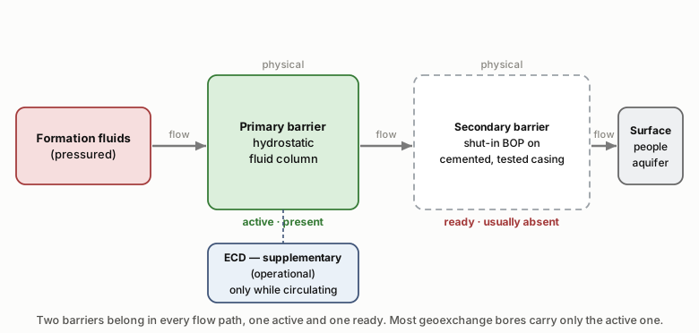
The ideal form of well control is a multi-barrier system, shown in Figure 6-1. When possible, drillers should use at least two barriers that cannot fail under the same conditions.
A barrier is any physical component or operational practice that prevents formation fluids from flowing unintentionally into the bore. There are three classes of barriers:
- Fluid (drilling fluid, grout)
- Mechanical (e.g., cemented and tested diverter, packers, plugs)
- Operational (hydrodynamic ECD, drilling fluid management)
Fluid barriers are primary barriers, because they are first in line to the formation and require no power to maintain. They can remain overbalanced and resist influx with nothing else in the bore. The first fluid barrier is always the density of the drilling fluid, which applies hydrostatic pressure to the formation to prevent or resist influx.
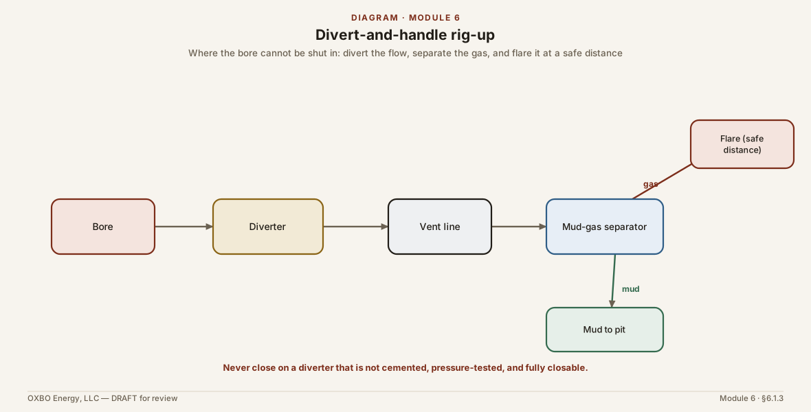
Mechanical barriers resist or redirect flow. They are most often temporary, and when permanent, they are generally combined with cement or grout. Mechanical barriers are secondary barriers. A diverter, as normally used, is not a barrier: it contains no pressure and stops no influx into the bore, it only routes flow that is already there. There is one way a diverter becomes a barrier. A diverter that is cemented, pressure tested, and able to be fully closed is functionally a single-element BOP, and it can be shut in for a limited time where the anticipated pressure is within its rating and the manufacturer and the AHJ permit it. A diverter that cannot be fully closed is never a barrier. Combined with a collection pit or tank, a mud-gas separator, and a flare it becomes a safe way to route and handle flow and to buy time, but it still contains nothing, and without those three it is only a re-routing mechanism that buys time until emergency services arrive.
Operational barriers are those actions that resist or prevent influx through crew action. These can include increasing frictional pressure in the bore by managing the pump rate (ECD), treating the drilling fluid with chemicals to maintain borehole stability, and circulating at sufficient rates to transport solids to the surface and to keep gas bubbles small and moving. The equivalent circulating density is a supplementary, or pseudo, barrier. It adds to the hydrostatic pressure of the primary fluid barrier while the pump runs, and it falls away when the pump stops, so it supplements the fluid barrier and does not stand as an independent one.
Air drilling, as performed in geothermal work, is generally a zero-barrier activity. It should be monitored closely and performed only in areas with well-known geology. Extra precautions should be taken around buildings, and gas monitoring should be required, not recommended.
6.1.4 Preparation on Paper
Before arriving on location, drillers should prepare for the risks specific to that location.
6.1.4.1 Desk Study Review
Drillers should receive and review the geologic prognosis before mobilizing personnel to the location. They should be familiar with the geologic layers, the fluids they contain, and the potential pressure sources and flow paths. The driller has a self-interest in understanding subsurface risk in advance. If the geologic prognosis does not provide enough information to understand pore pressure and fracture pressure, and to stage materials and equipment for well control, the driller should either ask for clarification or prepare for a reasonable worst-case scenario. Although the driller may have particular local knowledge, it is usually the engineer who chooses the location and depth, and therefore the scope and scale of the risk exposure.
Table 6-1 (placeholder). Desk-study inputs carried to location: formation tops, the pore-pressure and fracture-gradient profiles, the gas-bearing intervals, the MAMW, the planned mud weight and kill weight, and the maximum pipe-movement rates.
6.1.4.2 Fluid Preparation and Planning
The base of fresh water should be estimated as accurately as possible in the geologic prognosis. Drillers should be aware of the potential for inter-zonal communication that could damage or pollute the aquifer.
Unless specified by the engineer or the AHJ, drillers should plan a drilling fluid program to prevent or mitigate damage to freshwater aquifers. Unless casing is set and the aquifer is zonally isolated, drillers should use only fluids and additives allowed under NSF/ANSI/CAN Standard 60 or by the AHJ, whichever dominates. Where possible, the drilling fluid should include additives to ensure borehole stability in reactive formations such as shales, anhydrite, and some carbonates, and to counteract the effects of brines and salts.
Drilling fluid design is its own discipline, tightly coupled with geology, solids control, and well control. Drilling fluid suppliers regularly provide specialized training, design, and field services, and drillers are encouraged to consult with them as risk dictates.
6.1.4.3 Emergency Response Planning (ERP)
A well-formed ERP contains several key features.
Alerting and Alarming
Previous modules discuss the identification of influx but do not detail how alerting and alarming should be done. The means and methods of alerting and alarming may be unique to the AHJ, the customer, or the site. The following are some recommendations.
- Alerts should be timely, obvious, and relevant. The time from influx to surface expression in shallow bores is much faster than in deeper bores. If an influx is noted, it should be available to the driller and the crew promptly. Alerts should be hard to miss and should ideally use multiple modalities, including audio, visual, and other notifications. Alerts should avoid being annoying in a manner that leads drillers to ignore them.
- Alarms should include high-decibel, unique audio signals and flashing or strobing lights that can be discerned not only by the rig crew but by anyone within the reasonable influence of a potential well control event.
- In the event of influx or surface expression, the most critical alarms are for gas monitoring. While brines may cause the most long-lasting damage, they are a lower immediate threat to life. Methane and H2S monitors and alarms should be used on every bore, regardless of depth. They are inexpensive, easy to use, and can be body-worn or mounted on equipment for site-wide safety. The ability to identify combustible or asphyxiant gases before they reach explosive or toxic limits is potentially life-saving.
Rig Configuration
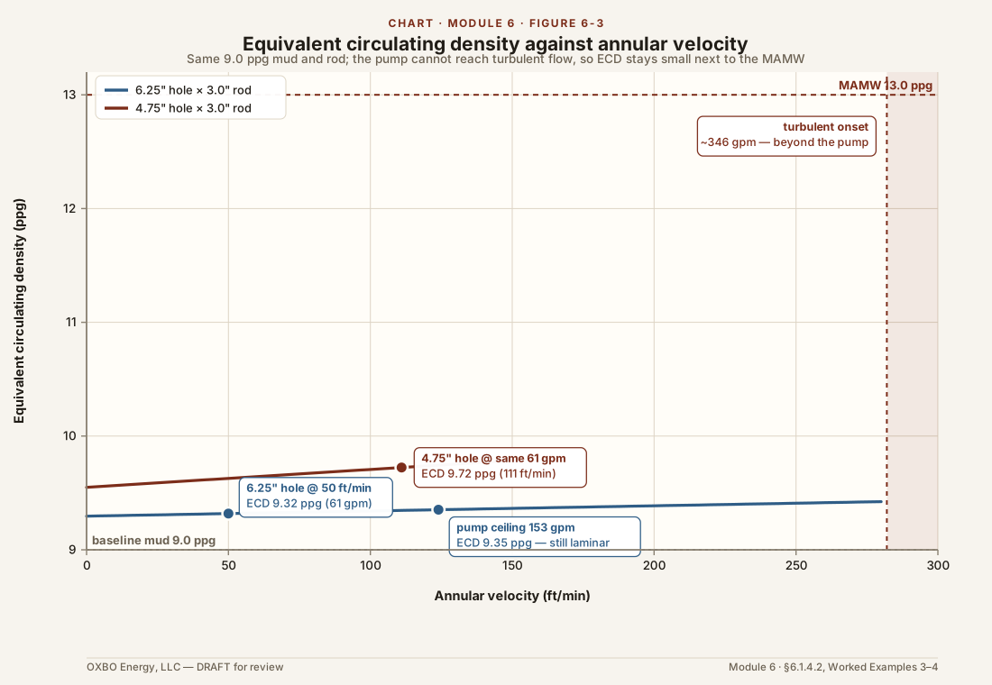
Rigs should be equipped with solids-control and fluid-management equipment proportional to the risk. This may include pits, mud hydration and mixing equipment, trip tanks, shakers, desanders and desilters, and centrifuges. These systems are critical to keep mud weight at the desired level. Failure to remove cuttings and other solids can result in a mud weight that leaves little or no well control margin, or that yields high or unmanageable ECDs. Rig pumps should be selected for effective solids transport, and with margin beyond that to add ECD as an auxiliary form of well control. A single rig pump may not reach the rate a meaningful contribution requires, particularly in a wide annulus, as Worked Example 3 shows, so an outboard or auxiliary pump may be needed.
Equipment Management
In the event of an out-of-control bore (a blowout), or when a bore is being brought under control, gases may reach explosive concentration in the atmosphere. The rig may become an ignition source. In the event of a large fluid influx from uncemented or poorly consolidated formations, the ground may compress, subside, or be undermined by flow.
The crew should know how to manage rig equipment to prevent unnecessary additional risk to life, health, property, and the environment. Rig manufacturers and operators are encouraged to equip rigs with simple, and where possible automatic, shutdown capabilities to prevent ignition. Because these wells do not intentionally target combustible fluids, a combustible atmosphere is not expected, and the classified-location electrical ratings that apply where such gas is expected are not required. Where the desk study does find gas, the hazard is nonetheless real, because it depends on whether gas is present, not on the target of the well, and the general duty to address a recognized hazard applies. The practical answer is the ignition-source control already described, and it is wise to have the shutdown also disable any electronics that are not intrinsically safe.
Control of Well
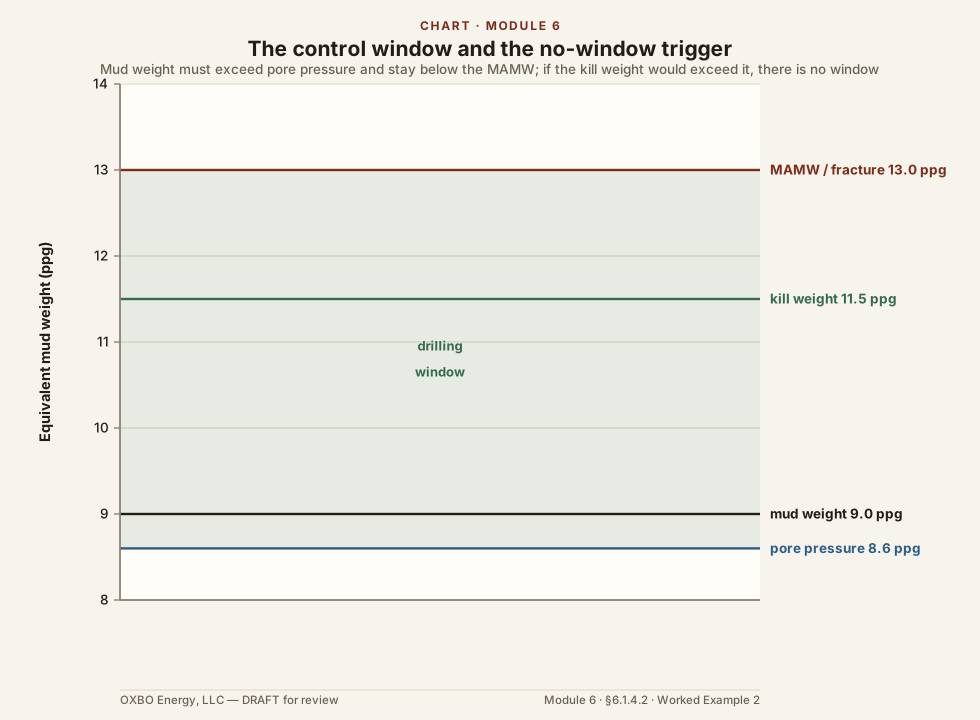
Drillers should calculate, in advance, the amount of weighting material required to control pressure with kill-weight mud, or mud of sufficient density to resist influx with hydrostatic pressure alone. The ceiling on that density is the maximum allowable mud weight (MAMW), the greatest weight the bore can hold without exceeding the fracture pressure at the shallowest exposed weak point. The MAMW is taken from the fracture gradient, or from a casing and shoe pressure test where one has been performed.
The amount of weighting material continuously on location should be 200% (two times) the amount required to raise the mud of the bore with the greatest volume to its MAMW. If multiple bores are being drilled concurrently, this should be increased proportionally to the number of rigs. This will ensure that every bore being drilled can be weighted to its MAMW, while providing a safety margin for leakoff, solids-control losses, and bore enlargement from instability or roughness.
Barite is used throughout this module as the example weighting agent, for its common use in well control. The driller should use a material of the required density that the AHJ has approved for the exposed formations.
Notation and formulae (weighting). starting mud weight (ppg); target mud weight (ppg); volume to be weighted (bbl); hole diameter (in); fracture gradient (psi/ft); barite mass (lb).
Equation (2) gives the hole capacity in barrels per foot. Equation (3) is for barite of 4.20 specific gravity, in which 1470 is the weight of a barrel of barite and 35 is its density in ppg.
Worked Example 1 — Minimum barite on location. Consider a 6.25-inch bore planned to a thousand feet, with surface casing at eighty feet, a fracture gradient at the shoe of 0.70 psi/ft, a drilling weight of 9.0 ppg, 3.0-inch ERW drill rod of 2.5-inch bore (a 0.25-inch wall), twenty barrels of active surface volume, and barite of 4.20 specific gravity as the weighting material.
The maximum allowable mud weight, from Eq. (1):
A design MAMW of 13.0 ppg is taken to hold a margin below fracture. The hole capacity, from Eq. (2):
The rod in the hole displaces its steel, so the mud is the hole less that steel, bbl/ft. Over a thousand feet the hole holds 35.3 barrels of mud, and with the twenty barrels at surface the system to be weighted is 55.3 barrels. The barite to raise that system from 9.0 to 13.0 ppg, from Eq. (3):
That is 148 hundred-pound sacks, rounding up, or about 7.4 tons. Applying the 200% rule, the minimum stocked on location is twice that, 296 sacks, or about 14.8 tons, for this single bore.
Site Preparation and Environmental Compliance
Drillers should, when required by the customer or the AHJ, or when they identify a reasonable risk to surface and navigable waters, take extra precautions to prevent and control spills and leaks. This should include both influx fluids and the fluids associated with their equipment, including fuels, lubricants, hydraulic oils, and other dangerous or hazardous fluids. If drilling near occupied structures, drillers should consider additional monitoring near those structures, especially in basements.
Site and Personnel Management
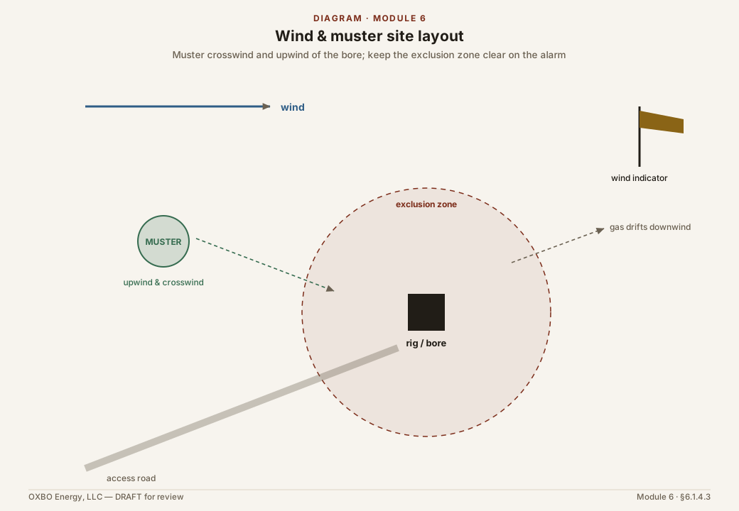
Drillers may not have control of the site if a construction manager or another organization is the project manager or prime contractor. Even where drillers do not control the site, they should retain as much stop-work and emergency authority as they can, and as their own safety requires, in proportion to the expected risk. Drillers should use wind direction indicators when toxic gases are reasonably expected. Drillers should establish muster points while drilling. These may change as bores are drilled and other construction activities commence. Drillers should coordinate with the other trades and with management, and should conspicuously post the current muster point so that affected personnel can be informed.
Third Party Emergency Services
The location and contact information for public emergency services and hospitals should be documented in advance and posted conspicuously. The address, driving directions, latitude, and longitude of the site should be posted with it. Drillers should coordinate with local emergency services in advance when the duration of the work justifies it. This may include informing fire services of the potential presence of hazardous bore fluids or operational materials.
6.2 Validation and Verification
Equipment is validated and verified before and during drilling, especially the emergency shutoffs, the diverters, the automatic flares, and the alarms.
6.3 Mitigation Methods
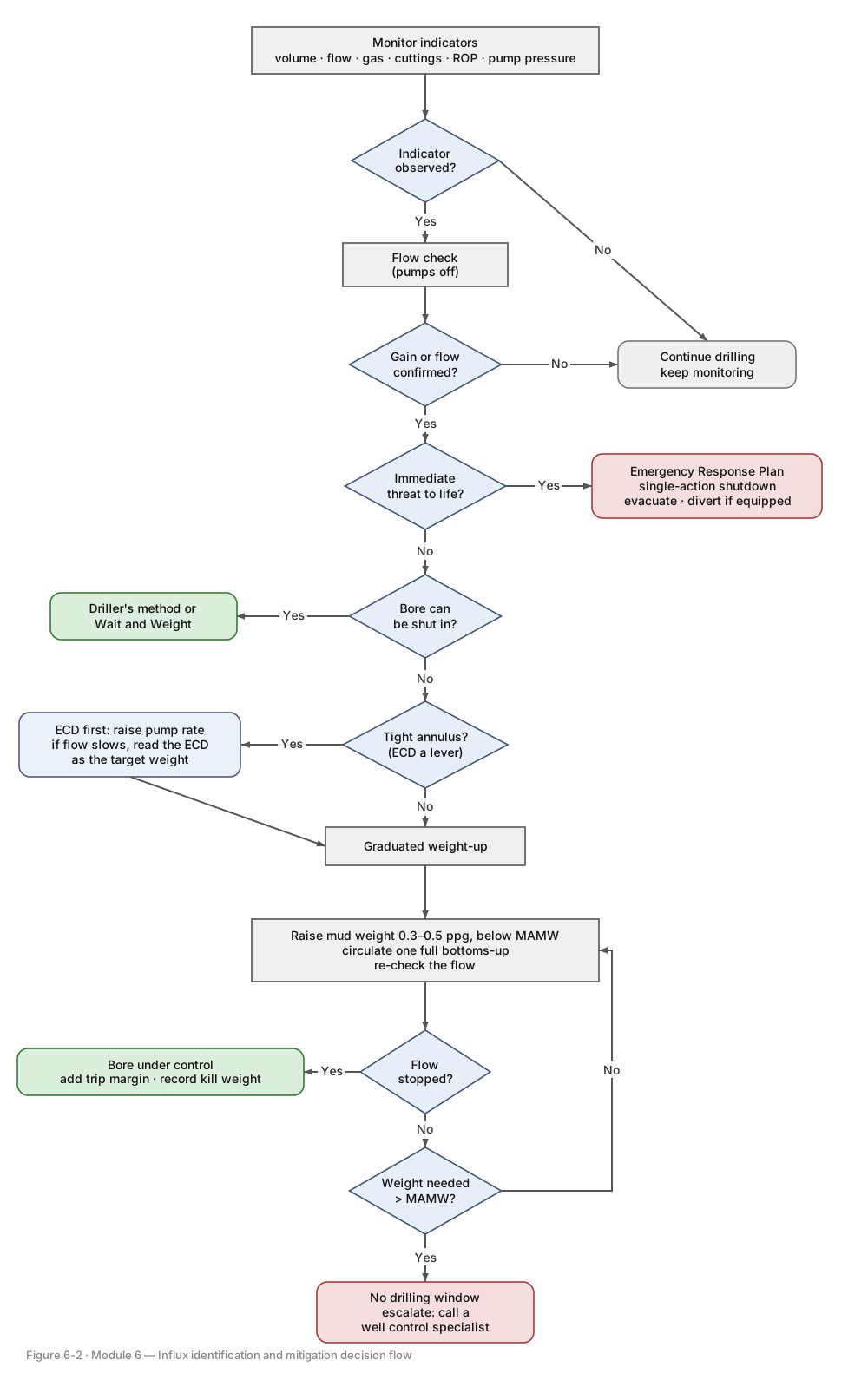
The response to a confirmed influx follows one decision flow, from the first indicator through the choice between dynamic control and emergency response, to control or escalation. That flow is shown in Figure 6-2, and the parts below describe it.
While Drilling
Prevention is always better than mitigation.
- The simplest and most effective way to identify and manage influx is to detect it early. The easiest time to observe signs of influx is at a connection when the pumps are off, in a flow check. It is an ideal time to sample the drilling fluid and record its rheological properties, such as density and viscosity. Drillers should perform flow checks regularly and proportionally to risk. It is recommended to perform a flow check no less than every 100 ft, or whenever there is a significant change in cuttings lithology, cuttings shape, rate of penetration, or other signals of influx. A few moments to observe the bore’s behavior can be a wise investment.
- Drillers are encouraged to develop and document best practices for managing surge and swab. Swab is the greater concern for influx, because pulling pipe lowers the bottomhole pressure, while running pipe raises it and risks losses instead. Drillers may consider governing the speed at which pipe is removed from the bore according to the expected risk. This is a common practice in mineral-well drilling.
If an influx is noted, and there is no immediate threat to life, such as an explosive gas concentration or an H2S or asphyxiant toxicity alarm, it is best to leave the drillpipe in the bore, since it is the only way to circulate and deliver weighted fluid.
- If the influx is dangerous, immediately engage the emergency response plan according to the identified risks.
After gas enters the bore, buoyancy governs it. The mechanism is introduced in Section 5.10. The gas rises. As it rises the confining pressure falls and the gas expands. The expanding gas displaces mud and lightens the column. The lighter column lowers the bottomhole pressure, and the lower pressure admits more gas. The effect compounds. It is largest in the final hundred feet, where a given rise produces the greatest expansion. Once gas is in the circulating system, raising the mud weight no longer removes it. The gas leaves only by being circulated to surface. On a rig with no blowout preventer and no weighting material, prevention is the only control.
The actual influx pressure cannot be determined by the methods available to mineral-well operations unless the bore can be shut in and the pressure read. Where the bore can be shut in and monitored, the driller’s method and the Wait and Weight method are proven, and they are referenced here.
Where the bore cannot be shut in, the kill weight is reached by a graduated weight-up while circulation continues, a dynamic approach distinct from the shut-in methods of item 3. The magnitudes below are suggestions. The actual call rests with the driller and what he sees, smells, hears, and feels, and he may take larger or smaller steps, or begin with the pump rather than the sack.
- On the first indicator, begin preparing weighting material and continue to circulate.
- In a tighter annulus the pump builds more equivalent circulating density, so raising the pump rate can be a first response. If a higher rate slows the flow, that gain is worth having while weighting material is prepared. The gain is modest, though. Worked Examples 3 and 4 show that even a tight geoexchange hole adds well under a pound per gallon, so the pump buys a little time and weighting remains the tool from the start.
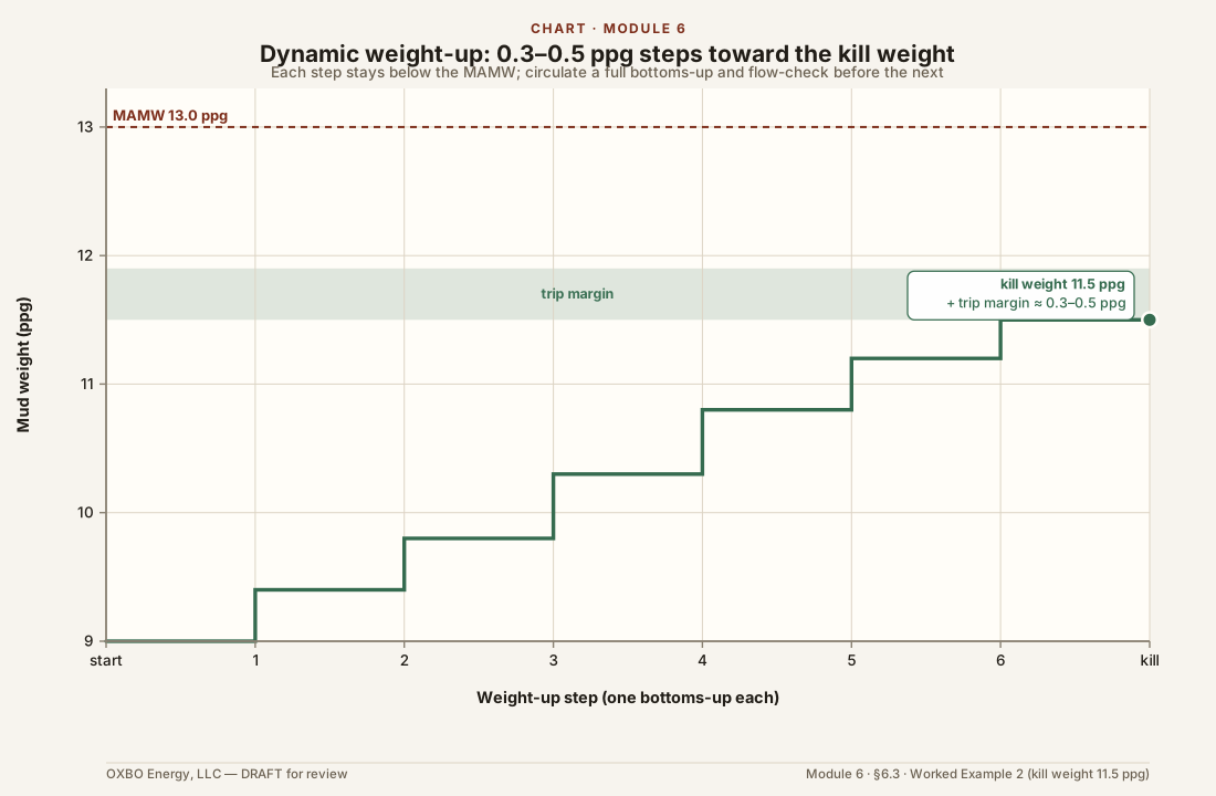
- Raise the mud weight in steps, on the order of 0.3 to 0.5 ppg at a time, each step held below the MAMW.
- After each step, circulate at least one full bottoms-up so the heavier mud reaches the bottom and returns to the surface, and read the returns.
- Check the flow after each bottoms-up. Where flow remains, raise the weight another step and circulate again.
- Stop when no flow remains. Add a trip margin, on the order of 0.3 to 0.5 ppg, and record the final kill weight.
- Where the weight needed to stop the flow would exceed the MAMW, there is no window, and the response moves to escalation rather than to more weight.
The bore is under control when no evidence of flow remains. The driller should document the rate and mud weight at each step, and should record the density of the kill-weight mud. This becomes the basis of mud weight for the other bores on the location, and serves to protect future drillers nearby.
If the influx cannot be controlled without exceeding the fracture gradient, or if the weighting materials have been exhausted and cannot be replenished, or if the surface pressure exceeds the equipment’s pressure ratings, or if the surface has been broached anywhere other than at the bore, or if the influx volume is expected to exceed the on-site spill-control capacity, the driller should call a well control specialist.
Worked Example 2 — Weighting up the working volume. Suppose the active system of the same bore holds 55.3 barrels at 9.0 ppg, and an influx indicates a kill weight of 11.5 ppg. The barite to add, from Eq. (3):
That rounds up to 87 hundred-pound sacks, about 4.3 tons. As the barite is added the volume grows, so the crew confirms the pits can hold it.
Notation and formulae (hydraulics). flow (gpm); annular velocity (ft/min); annular velocity (ft/s); hole diameter (in); pipe outside diameter (in); pump displacement (gal/stroke); pump speed (strokes/min); volumetric efficiency; annular capacity (bbl/ft); depth (ft); plastic viscosity (cp); yield point (lbf/100 ft²); effective viscosity (cp); Reynolds number; mud weight (ppg); annular friction (psi); ECD equivalent circulating density (ppg).
Equation (9) is the Bingham-plastic laminar form, valid where is below about 2,100. The field forms are drawn from Applied Drilling Engineering, Chapter 4.
Worked Example 3 — Pump rate, bottoms-up, and the ECD from a rate increase. Consider the same 6.25-inch bore to a thousand feet, with 3.0-in outside-diameter ERW drill rod of 2.5-in inside diameter, drilling mud at 9.0 ppg, and a baseline annular velocity of 50 ft/min. The plastic viscosity and yield point are taken as cp and lbf/100 ft², representative of a light bentonite mud and replaced in practice by the values measured on the rig. The pump is a Gardner Denver TEE triplex, a 125-BHP class pump typical of a water-well or geothermal rig, with a three-inch plunger that displaces 0.459 gallons per stroke at 95% volumetric efficiency.
The annular capacity, from Eq. (6):
The flow at the baseline 50 ft/min, from Eq. (5) solved for :
The pump speed, from Eq. (4):
This is within the pump’s 350-SPM rating. The bottoms-up volume is the annulus from bit to surface:
The bottoms-up time is minutes, which equals . The effective viscosity and Reynolds number, from Eqs. (7) and (8):
At , far below 2,100, the annulus flows laminar. The annular friction at 50 ft/min ( ft/s), from Eq. (9):
Over the thousand feet that is 16.6 psi. The equivalent circulating density, from Eq. (10):
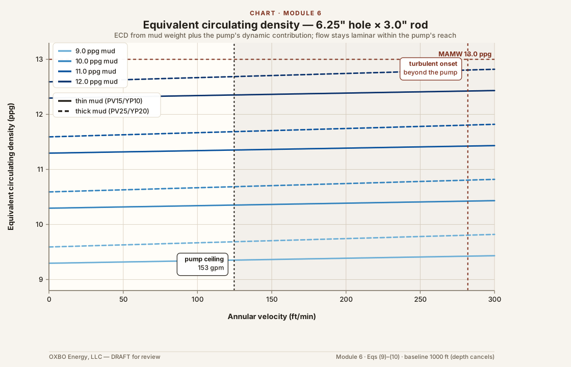
A 10% increase in pump rate raises the flow to gpm and the annular velocity to 55 ft/min ( ft/s). Re-evaluating Eqs. (9) and (10) at that velocity gives a friction of 16.7 psi and an ECD of 9.32 ppg, an increase of only about 0.002 ppg. In laminar flow only the velocity term of Eq. (9) grows with rate, so a meaningful ECD would require turbulent flow. For this mud and geometry the annulus turns turbulent near , at an annular velocity of about 282 ft/min, or a flow near 346 gpm. That flow is beyond the pump: at its rated 350 SPM the pump delivers, from Eq. (4):
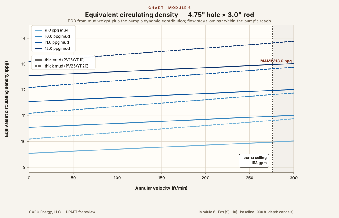
Reaching 346 gpm would take about 790 SPM, more than twice the rating. At the pump ceiling of 153 gpm the annular velocity is 124 ft/min ( ft/s), the flow is still laminar with , the friction is 18.3 psi, and the ECD is:
which is only 0.03 ppg above the baseline.
At these low annular rates the flow is laminar, and the velocity-dependent term of the friction is small next to the yield-point term. Circulating at 50 ft/min adds about 0.32 ppg of equivalent dynamic density, near 17 psi at a thousand feet, while a further 10% of pump rate adds only about 0.002 ppg. A meaningful ECD would need turbulent flow, and the pump cannot reach it: at its ceiling the 6.25-inch annulus is still laminar, and the ECD has risen only to 9.35 ppg. The rig is pump-limited in this hole, so the pressure that resists an influx comes from mud weight, and the pump serves to carry gas out and keep the cuttings moving rather than to add bottomhole pressure.
A small rod in a large hole leaves a large annular area, so a given pump output produces a low annular velocity. That weakens both the transport of cuttings to the surface and the ECD the pump can build. A tighter annulus, from larger rod or a smaller hole, would raise the velocity for the same output and strengthen both.
Worked Example 4 — The same pump setting in a tighter hole. Take Worked Example 3 and change only the hole, from 6.25 inches to 4.75, keeping the same 3.0-in rod, the same 9.0 ppg mud, and the same pump setting of 141 SPM, or 61.4 gpm. The annular capacity, from Eq. (6):
The annular velocity at the same 61.4 gpm, from Eq. (5):
against 50 ft/min in the 6.25-inch hole. Bottoms-up is barrels, cleared in minutes, against 20 minutes before. The flow is still laminar, from Eqs. (7) and (8):
The annular friction, from Eq. (9), and the ECD, from Eq. (10):
At the same pump setting the 4.75-inch hole carries 111 ft/min against 50, clears bottoms-up in under half the time, and builds an ECD of 9.72 ppg against 9.32, a dynamic contribution of 0.72 ppg against 0.32. The tighter annulus does turn the pump into a larger lever, and the faster bottoms-up and better cuttings transport are real gains. Even so, the flow is still laminar and the ECD sits 3.28 ppg below the 13.0 MAMW, so the pump has not become a substitute for mud weight and does not threaten the formation. In both holes the rig is pump-limited, and the density that resists an influx comes from the mud weight, not the pump.
While Installing Tubulars
The ability to detect and respond to influx is reduced once the drillpipe has been removed from the bore. The worst influx events have occurred during these operations. Installing casing is much more likely to cause a surge than drilling is, and much more likely than running a u-tube loop.
The primary detection tool while running or pulling pipe is a trip sheet. As pipe is pulled, the hole should take the volume of the steel removed. As pipe is run, the hole should return that volume. A hole that takes less than the calculated volume on a pull is taking a kick, and one that takes more on a run is losing fluid. The trip sheet is arithmetic, not equipment, and it is the earliest indicator available on an uninstrumented rig. Gains and losses are watched more carefully here than while drilling, at the tanks, the pits, and the bore.
Insertion force, or suspended load, is a second cue, and often one the crew feels directly. An HDPE loop is buoyant and is pushed into the bore rather than lowered, frequently by hand, so its resistance is felt and seen as it advances, in the effort required, in buckling, and in sticking. A lighter column from an influx reduces the buoyancy that opposes the loop, so a sudden change in the insertion force can mark it. Steel casing, lowered under its own weight, shows the same lighter column as a change in the suspended load. The trip sheet volume stays the primary indicator, with the felt cue reinforcing it.
The response is constrained, because the drillpipe is out and conventional circulation is not available. The crew stops running or pulling, confirms the gain with a flow check, and keeps the hole full with kill-weight fluid from the surface to restore hydrostatic head. Where a conduit is in the bore, a tremie, the loop, or coiled tubing, kill-weight fluid is pumped through it, though the ECD it can deliver is limited. Where the flow cannot be brought under control by these means, the response moves to diversion and evacuation under the emergency response plan.
Installing tubulars is more likely to occur at the end of a work day than drilling is, which makes human factors a much more important consideration. Fatigue plays a role, but safety bias plays a larger one. It is easy to become complacent on a bore that gave no well control trouble while drilling. Vigilance during tubular installation is critical.
While Placing the Column
The placement of the zonal isolation column is discussed in the zonal isolation module.
Appendix A — Sample Pre-Spud Equipment and Verification Checklist
This is a sample checklist, completed before every bore, confirming that the equipment and materials described in this module are present and have been field-verified. It is illustrative rather than exhaustive, and it is adapted to the expected risk and to the AHJ’s requirements. Each device or barrier is verified by test, with the date and initials recorded.
| Item | Present | Field-verified & dated |
|---|---|---|
| Competency and authority | ||
| Named, trained crew; well control and H2S certifications current | ☐ | ☐ |
| Station bill assigned; each member’s first action known | ☐ | ☐ |
| Stop-work authority named, independent of cost and schedule | ☐ | ☐ |
| Desk study carried to location | ||
| Formation sequence, pore pressure, and gas intervals reviewed | ☐ | ☐ |
| MAMW and kill weight known; no-window check completed | ☐ | ☐ |
| Maximum pipe-movement rates stated | ☐ | ☐ |
| Weighting and fluid | ||
| Weighting material stocked to 200% of the MAMW requirement | ☐ | ☐ |
| Mixing capacity and achievable rate confirmed | ☐ | ☐ |
| Lost-circulation and plugging material on hand | ☐ | ☐ |
| Additives compliant with NSF/ANSI/CAN 60 or the AHJ | ☐ | ☐ |
| Monitoring and alarms | ||
| Pit or tank marked for gain detection; volumes known | ☐ | ☐ |
| Methane and H2S monitors functional | ☐ | ☐ |
| Audible and visual alarms tested | ☐ | ☐ |
| Trip sheet prepared; fill and displacement volumes calculated | ☐ | ☐ |
| Ignition control | ||
| Single-action emergency shutdown tested; disables all ignition sources | ☐ | ☐ |
| Diesel air-intake shutoffs tested, where diesels are used | ☐ | ☐ |
| Non-intrinsically-safe electronics placed on the shutdown circuit | ☐ | ☐ |
| Diverter, separator, and flare, where used | ||
| Diverter foundation cemented and pressure tested | ☐ | ☐ |
| Mud-gas separator seal leg full; capacity checked against the anticipated rate | ☐ | ☐ |
| Flare placed, oriented, and demonstrated this operating day | ☐ | ☐ |
| Shut-in-rated unit: the three conditions of Section 6.1.3 documented | ☐ | ☐ |
| Site and emergency response | ||
| Wind indicators set; muster points posted | ☐ | ☐ |
| Emergency services and hospital contacts posted with the site location | ☐ | ☐ |
| Notification chain written and current | ☐ | ☐ |
| Sign-off | ||
| Completed and signed before this bore by the stop-work authority | ☐ | ☐ |
Appendix B — Barite Weight-Up Tables
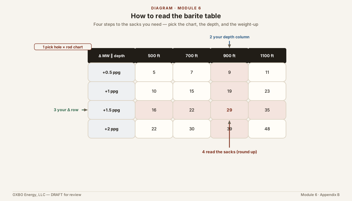
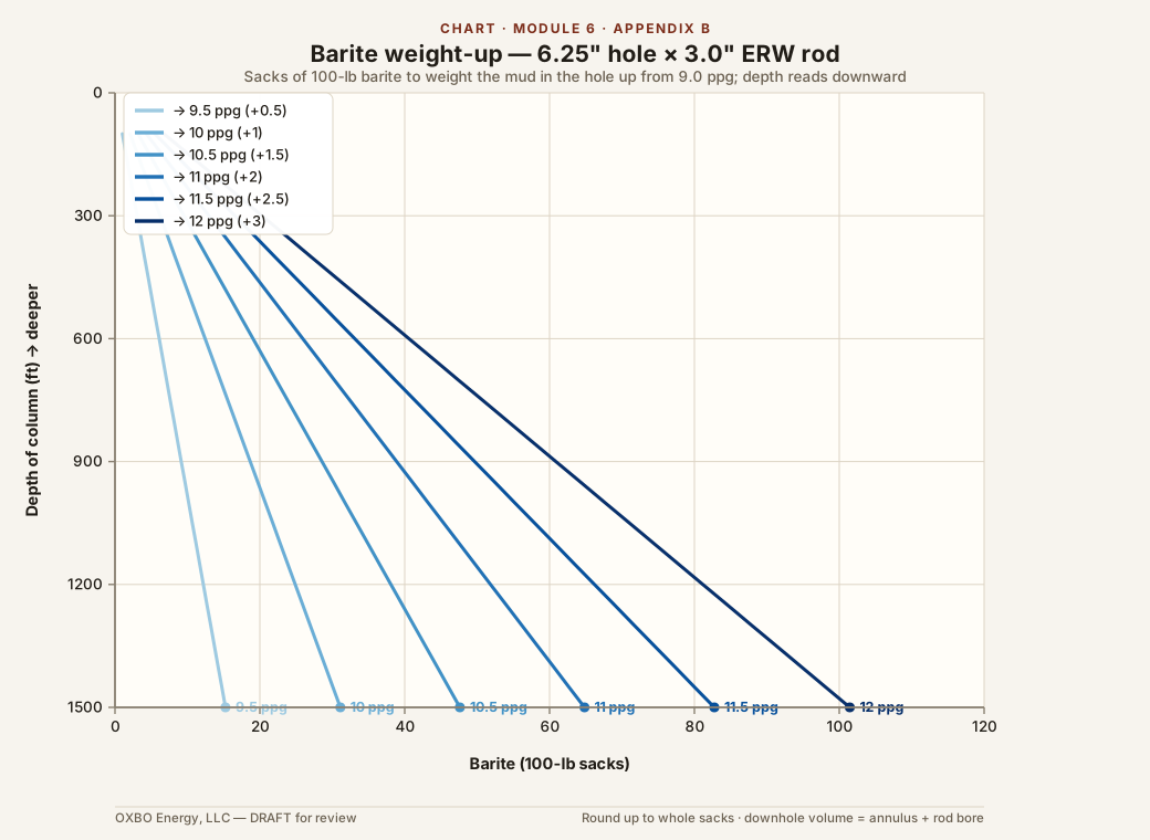
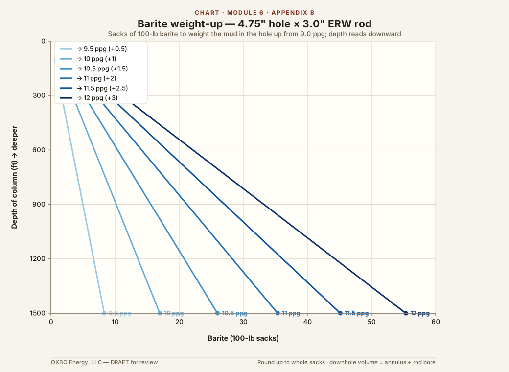
These tables give the barite, in hundred-pound sacks, required to raise the mud in the hole from a 9.0 ppg baseline to a higher weight, for the bore and rod sizes common in geoexchange work. They apply Eq. (3) to the mud volume in the hole, taken as the annulus plus the rod bore, which is the hole capacity less the rod steel. Depth runs across the top in hundred-foot steps. The mud-weight increase runs down the side in 0.2 ppg steps. Values are rounded up to whole sacks.
The dimensions follow the survey of drill rod and bit sizes used in this work. Hole diameters are the standard PDC bit sizes nearest four and six inches, 4.75 in and 6.25 in. Drill rod is light ERW welded tube, thinner than oilfield drill pipe, taken here at a 0.25-inch wall applied to every size. Surface and pit volume is not included, so a full active-system weight-up needs more than a table shows. The same calculation, with any rod or hole entered directly, is in the companion workbook, Barite_WeightUp_Tables.xlsx.
B.1 4.75-inch hole, 2-3/8-inch rod (2.375 / 1.875)
| Δ ppg | 100 | 200 | 300 | 400 | 500 | 600 | 700 | 800 | 900 | 1000 | 1100 | 1200 | 1300 | 1400 | 1500 |
|---|---|---|---|---|---|---|---|---|---|---|---|---|---|---|---|
| +0.2 | 1 | 1 | 1 | 1 | 2 | 2 | 2 | 2 | 3 | 3 | 3 | 3 | 3 | 4 | 4 |
| +0.4 | 1 | 1 | 2 | 2 | 3 | 3 | 4 | 4 | 5 | 5 | 6 | 6 | 6 | 7 | 7 |
| +0.6 | 1 | 2 | 3 | 3 | 4 | 5 | 5 | 6 | 7 | 7 | 8 | 9 | 9 | 10 | 11 |
| +0.8 | 1 | 2 | 3 | 4 | 5 | 6 | 7 | 8 | 9 | 10 | 11 | 12 | 13 | 13 | 14 |
| +1.0 | 2 | 3 | 4 | 5 | 6 | 8 | 9 | 10 | 11 | 12 | 13 | 15 | 16 | 17 | 18 |
| +1.2 | 2 | 3 | 5 | 6 | 8 | 9 | 10 | 12 | 13 | 15 | 16 | 17 | 19 | 20 | 22 |
| +1.4 | 2 | 4 | 5 | 7 | 9 | 10 | 12 | 14 | 15 | 17 | 19 | 20 | 22 | 24 | 25 |
| +1.6 | 2 | 4 | 6 | 8 | 10 | 12 | 14 | 16 | 18 | 20 | 22 | 23 | 25 | 27 | 29 |
| +1.8 | 3 | 5 | 7 | 9 | 11 | 14 | 16 | 18 | 20 | 22 | 24 | 27 | 29 | 31 | 33 |
| +2.0 | 3 | 5 | 8 | 10 | 13 | 15 | 18 | 20 | 22 | 25 | 27 | 30 | 32 | 35 | 37 |
| +2.2 | 3 | 6 | 9 | 11 | 14 | 17 | 19 | 22 | 25 | 27 | 30 | 33 | 36 | 38 | 41 |
| +2.4 | 3 | 6 | 9 | 12 | 15 | 18 | 21 | 24 | 27 | 30 | 33 | 36 | 39 | 42 | 45 |
| +2.6 | 4 | 7 | 10 | 13 | 17 | 20 | 23 | 26 | 30 | 33 | 36 | 39 | 43 | 46 | 49 |
| +2.8 | 4 | 8 | 11 | 15 | 18 | 22 | 25 | 29 | 32 | 36 | 39 | 43 | 46 | 50 | 53 |
| +3.0 | 4 | 8 | 12 | 16 | 20 | 23 | 27 | 31 | 35 | 39 | 42 | 46 | 50 | 54 | 58 |
B.2 4.75-inch hole, 3.0-inch ERW rod (3.000 / 2.500)
| Δ ppg | 100 | 200 | 300 | 400 | 500 | 600 | 700 | 800 | 900 | 1000 | 1100 | 1200 | 1300 | 1400 | 1500 |
|---|---|---|---|---|---|---|---|---|---|---|---|---|---|---|---|
| +0.2 | 1 | 1 | 1 | 1 | 2 | 2 | 2 | 2 | 2 | 3 | 3 | 3 | 3 | 4 | 4 |
| +0.4 | 1 | 1 | 2 | 2 | 3 | 3 | 4 | 4 | 4 | 5 | 5 | 6 | 6 | 7 | 7 |
| +0.6 | 1 | 2 | 3 | 3 | 4 | 5 | 5 | 6 | 7 | 7 | 8 | 9 | 9 | 10 | 11 |
| +0.8 | 1 | 2 | 3 | 4 | 5 | 6 | 7 | 8 | 9 | 9 | 10 | 11 | 12 | 13 | 14 |
| +1.0 | 2 | 3 | 4 | 5 | 6 | 7 | 8 | 10 | 11 | 12 | 13 | 14 | 15 | 16 | 17 |
| +1.2 | 2 | 3 | 5 | 6 | 7 | 9 | 10 | 11 | 13 | 14 | 16 | 17 | 18 | 20 | 21 |
| +1.4 | 2 | 4 | 5 | 7 | 9 | 10 | 12 | 13 | 15 | 17 | 18 | 20 | 21 | 23 | 25 |
| +1.6 | 2 | 4 | 6 | 8 | 10 | 12 | 13 | 15 | 17 | 19 | 21 | 23 | 25 | 26 | 28 |
| +1.8 | 3 | 5 | 7 | 9 | 11 | 13 | 15 | 17 | 19 | 22 | 24 | 26 | 28 | 30 | 32 |
| +2.0 | 3 | 5 | 8 | 10 | 12 | 15 | 17 | 19 | 22 | 24 | 26 | 29 | 31 | 34 | 36 |
| +2.2 | 3 | 6 | 8 | 11 | 14 | 16 | 19 | 21 | 24 | 27 | 29 | 32 | 34 | 37 | 40 |
| +2.4 | 3 | 6 | 9 | 12 | 15 | 18 | 21 | 24 | 26 | 29 | 32 | 35 | 38 | 41 | 44 |
| +2.6 | 4 | 7 | 10 | 13 | 16 | 19 | 23 | 26 | 29 | 32 | 35 | 38 | 41 | 45 | 48 |
| +2.8 | 4 | 7 | 11 | 14 | 18 | 21 | 24 | 28 | 31 | 35 | 38 | 41 | 45 | 48 | 52 |
| +3.0 | 4 | 8 | 12 | 15 | 19 | 23 | 26 | 30 | 34 | 37 | 41 | 45 | 48 | 52 | 56 |
B.3 6.25-inch hole, 3.0-inch ERW rod (3.000 / 2.500)
| Δ ppg | 100 | 200 | 300 | 400 | 500 | 600 | 700 | 800 | 900 | 1000 | 1100 | 1200 | 1300 | 1400 | 1500 |
|---|---|---|---|---|---|---|---|---|---|---|---|---|---|---|---|
| +0.2 | 1 | 1 | 2 | 2 | 3 | 3 | 3 | 4 | 4 | 5 | 5 | 5 | 6 | 6 | 7 |
| +0.4 | 1 | 2 | 3 | 4 | 5 | 5 | 6 | 7 | 8 | 9 | 9 | 10 | 11 | 12 | 13 |
| +0.6 | 2 | 3 | 4 | 5 | 7 | 8 | 9 | 10 | 12 | 13 | 14 | 15 | 16 | 18 | 19 |
| +0.8 | 2 | 4 | 5 | 7 | 9 | 10 | 12 | 14 | 15 | 17 | 19 | 20 | 22 | 24 | 25 |
| +1.0 | 3 | 5 | 7 | 9 | 11 | 13 | 15 | 17 | 19 | 21 | 23 | 25 | 27 | 30 | 32 |
| +1.2 | 3 | 6 | 8 | 11 | 13 | 16 | 18 | 21 | 23 | 26 | 28 | 31 | 33 | 36 | 38 |
| +1.4 | 3 | 6 | 9 | 12 | 15 | 18 | 21 | 24 | 27 | 30 | 33 | 36 | 39 | 42 | 45 |
| +1.6 | 4 | 7 | 11 | 14 | 18 | 21 | 24 | 28 | 31 | 35 | 38 | 41 | 45 | 48 | 52 |
| +1.8 | 4 | 8 | 12 | 16 | 20 | 24 | 27 | 31 | 35 | 39 | 43 | 47 | 51 | 54 | 58 |
| +2.0 | 5 | 9 | 13 | 18 | 22 | 26 | 31 | 35 | 39 | 44 | 48 | 52 | 57 | 61 | 65 |
| +2.2 | 5 | 10 | 15 | 20 | 24 | 29 | 34 | 39 | 44 | 48 | 53 | 58 | 63 | 68 | 72 |
| +2.4 | 6 | 11 | 16 | 22 | 27 | 32 | 37 | 43 | 48 | 53 | 59 | 64 | 69 | 74 | 80 |
| +2.6 | 6 | 12 | 18 | 24 | 29 | 35 | 41 | 47 | 52 | 58 | 64 | 70 | 75 | 81 | 87 |
| +2.8 | 7 | 13 | 19 | 26 | 32 | 38 | 44 | 51 | 57 | 63 | 69 | 76 | 82 | 88 | 94 |
| +3.0 | 7 | 14 | 21 | 28 | 34 | 41 | 48 | 55 | 61 | 68 | 75 | 82 | 88 | 95 | 102 |
B.4 6.25-inch hole, 2-3/8-inch rod (2.375 / 1.875)
| Δ ppg | 100 | 200 | 300 | 400 | 500 | 600 | 700 | 800 | 900 | 1000 | 1100 | 1200 | 1300 | 1400 | 1500 |
|---|---|---|---|---|---|---|---|---|---|---|---|---|---|---|---|
| +0.2 | 1 | 1 | 2 | 2 | 3 | 3 | 3 | 4 | 4 | 5 | 5 | 5 | 6 | 6 | 7 |
| +0.4 | 1 | 2 | 3 | 4 | 5 | 5 | 6 | 7 | 8 | 9 | 10 | 10 | 11 | 12 | 13 |
| +0.6 | 2 | 3 | 4 | 5 | 7 | 8 | 9 | 10 | 12 | 13 | 14 | 15 | 17 | 18 | 19 |
| +0.8 | 2 | 4 | 6 | 7 | 9 | 11 | 12 | 14 | 16 | 17 | 19 | 21 | 22 | 24 | 26 |
| +1.0 | 3 | 5 | 7 | 9 | 11 | 13 | 15 | 17 | 19 | 22 | 24 | 26 | 28 | 30 | 32 |
| +1.2 | 3 | 6 | 8 | 11 | 13 | 16 | 18 | 21 | 23 | 26 | 29 | 31 | 34 | 36 | 39 |
| +1.4 | 4 | 7 | 10 | 13 | 16 | 19 | 22 | 25 | 28 | 31 | 34 | 37 | 40 | 43 | 46 |
| +1.6 | 4 | 7 | 11 | 14 | 18 | 21 | 25 | 28 | 32 | 35 | 39 | 42 | 45 | 49 | 52 |
| +1.8 | 4 | 8 | 12 | 16 | 20 | 24 | 28 | 32 | 36 | 40 | 44 | 48 | 52 | 55 | 59 |
| +2.0 | 5 | 9 | 14 | 18 | 22 | 27 | 31 | 36 | 40 | 44 | 49 | 53 | 58 | 62 | 66 |
| +2.2 | 5 | 10 | 15 | 20 | 25 | 30 | 35 | 40 | 44 | 49 | 54 | 59 | 64 | 69 | 74 |
| +2.4 | 6 | 11 | 17 | 22 | 27 | 33 | 38 | 43 | 49 | 54 | 60 | 65 | 70 | 76 | 81 |
| +2.6 | 6 | 12 | 18 | 24 | 30 | 36 | 42 | 47 | 53 | 59 | 65 | 71 | 77 | 83 | 88 |
| +2.8 | 7 | 13 | 20 | 26 | 32 | 39 | 45 | 51 | 58 | 64 | 71 | 77 | 83 | 90 | 96 |
| +3.0 | 7 | 14 | 21 | 28 | 35 | 42 | 49 | 56 | 62 | 69 | 76 | 83 | 90 | 97 | 104 |
B.5 6.25-inch hole, 2-7/8-inch rod (2.875 / 2.375)
| Δ ppg | 100 | 200 | 300 | 400 | 500 | 600 | 700 | 800 | 900 | 1000 | 1100 | 1200 | 1300 | 1400 | 1500 |
|---|---|---|---|---|---|---|---|---|---|---|---|---|---|---|---|
| +0.2 | 1 | 1 | 2 | 2 | 3 | 3 | 3 | 4 | 4 | 5 | 5 | 5 | 6 | 6 | 7 |
| +0.4 | 1 | 2 | 3 | 4 | 5 | 5 | 6 | 7 | 8 | 9 | 9 | 10 | 11 | 12 | 13 |
| +0.6 | 2 | 3 | 4 | 5 | 7 | 8 | 9 | 10 | 12 | 13 | 14 | 15 | 16 | 18 | 19 |
| +0.8 | 2 | 4 | 5 | 7 | 9 | 10 | 12 | 14 | 15 | 17 | 19 | 20 | 22 | 24 | 25 |
| +1.0 | 3 | 5 | 7 | 9 | 11 | 13 | 15 | 17 | 19 | 21 | 23 | 25 | 28 | 30 | 32 |
| +1.2 | 3 | 6 | 8 | 11 | 13 | 16 | 18 | 21 | 23 | 26 | 28 | 31 | 33 | 36 | 38 |
| +1.4 | 3 | 6 | 9 | 12 | 15 | 18 | 21 | 24 | 27 | 30 | 33 | 36 | 39 | 42 | 45 |
| +1.6 | 4 | 7 | 11 | 14 | 18 | 21 | 24 | 28 | 31 | 35 | 38 | 41 | 45 | 48 | 52 |
| +1.8 | 4 | 8 | 12 | 16 | 20 | 24 | 28 | 31 | 35 | 39 | 43 | 47 | 51 | 55 | 59 |
| +2.0 | 5 | 9 | 14 | 18 | 22 | 27 | 31 | 35 | 40 | 44 | 48 | 53 | 57 | 61 | 66 |
| +2.2 | 5 | 10 | 15 | 20 | 25 | 29 | 34 | 39 | 44 | 49 | 53 | 58 | 63 | 68 | 73 |
| +2.4 | 6 | 11 | 16 | 22 | 27 | 32 | 38 | 43 | 48 | 53 | 59 | 64 | 69 | 75 | 80 |
| +2.6 | 6 | 12 | 18 | 24 | 29 | 35 | 41 | 47 | 53 | 58 | 64 | 70 | 76 | 81 | 87 |
| +2.8 | 7 | 13 | 19 | 26 | 32 | 38 | 44 | 51 | 57 | 63 | 70 | 76 | 82 | 88 | 95 |
| +3.0 | 7 | 14 | 21 | 28 | 34 | 41 | 48 | 55 | 62 | 68 | 75 | 82 | 89 | 96 | 102 |
B.6 6.25-inch hole, 3-1/2-inch rod (3.500 / 3.000)
| Δ ppg | 100 | 200 | 300 | 400 | 500 | 600 | 700 | 800 | 900 | 1000 | 1100 | 1200 | 1300 | 1400 | 1500 |
|---|---|---|---|---|---|---|---|---|---|---|---|---|---|---|---|
| +0.2 | 1 | 1 | 2 | 2 | 2 | 3 | 3 | 4 | 4 | 4 | 5 | 5 | 6 | 6 | 6 |
| +0.4 | 1 | 2 | 3 | 4 | 4 | 5 | 6 | 7 | 8 | 8 | 9 | 10 | 11 | 12 | 12 |
| +0.6 | 2 | 3 | 4 | 5 | 7 | 8 | 9 | 10 | 11 | 13 | 14 | 15 | 16 | 17 | 19 |
| +0.8 | 2 | 4 | 5 | 7 | 9 | 10 | 12 | 13 | 15 | 17 | 18 | 20 | 22 | 23 | 25 |
| +1.0 | 3 | 5 | 7 | 9 | 11 | 13 | 15 | 17 | 19 | 21 | 23 | 25 | 27 | 29 | 31 |
| +1.2 | 3 | 5 | 8 | 10 | 13 | 15 | 18 | 20 | 23 | 25 | 28 | 30 | 33 | 35 | 38 |
| +1.4 | 3 | 6 | 9 | 12 | 15 | 18 | 21 | 24 | 27 | 30 | 33 | 35 | 38 | 41 | 44 |
| +1.6 | 4 | 7 | 11 | 14 | 17 | 21 | 24 | 27 | 31 | 34 | 37 | 41 | 44 | 47 | 51 |
| +1.8 | 4 | 8 | 12 | 16 | 20 | 23 | 27 | 31 | 35 | 39 | 42 | 46 | 50 | 54 | 58 |
| +2.0 | 5 | 9 | 13 | 18 | 22 | 26 | 30 | 35 | 39 | 43 | 47 | 52 | 56 | 60 | 64 |
| +2.2 | 5 | 10 | 15 | 19 | 24 | 29 | 34 | 38 | 43 | 48 | 53 | 57 | 62 | 67 | 71 |
| +2.4 | 6 | 11 | 16 | 21 | 27 | 32 | 37 | 42 | 47 | 53 | 58 | 63 | 68 | 73 | 79 |
| +2.6 | 6 | 12 | 18 | 23 | 29 | 35 | 40 | 46 | 52 | 57 | 63 | 69 | 74 | 80 | 86 |
| +2.8 | 7 | 13 | 19 | 25 | 31 | 38 | 44 | 50 | 56 | 62 | 68 | 75 | 81 | 87 | 93 |
| +3.0 | 7 | 14 | 21 | 27 | 34 | 41 | 47 | 54 | 61 | 67 | 74 | 81 | 87 | 94 | 101 |
Key References
International Association of Drilling Contractors. Well Control Barrier Philosophy. IADC. https://iadc.org/wp-content/uploads/2020/12/Well-Control-Barrier-Philosophy.pdf
International Association of Drilling Contractors. Drilling Guide (example). IADC. https://iadc.org/wp-content/uploads/2020/04/DrillGuide_Example.pdf
NSF/ANSI/CAN 60, Drinking Water Treatment Chemicals — Health Effects. NSF International.
Occupational Safety and Health Administration. Hazardous (Classified) Locations, 29 CFR 1910.307 and 29 CFR 1926.407; and the General Duty Clause, Occupational Safety and Health Act of 1970, Section 5(a)(1).
Bourgoyne, A. T., Millheim, K. K., Chenevert, M. E., and Young, F. S. Applied Drilling Engineering. SPE Textbook Series, Vol. 2. Society of Petroleum Engineers. (Chapter 4, Drilling Hydraulics — pump output, annular velocity, frictional pressure loss, and equivalent circulating density.)
IADC Drilling Manual. International Association of Drilling Contractors. (Hydraulics and pump-output references.)
Gardner Denver. TEE (GD-125T) Triplex Pump technical data sheet. (Plunger output and rated speed used in Worked Examples 3 and 4.)
This module is © 2026 Nathan Zenero, OXBO Energy, LLC and is licensed under the Creative Commons Attribution-NonCommercial 4.0 International license (CC BY-NC 4.0), on the terms stated in Module 0. Requests for commercial licensing, submissions for the public errata, and accounts of encountered influx may be sent to nathan@oxbo.energy.