
Author: Nathan Zenero, OXBO Energy, LLC
Audience. Written for working geoexchange and water-well drillers and their crews, and for the contractors, design engineers, specifiers, and regulatory authorities who share responsibility for the boreholes they construct.
Detecting the Influx
Module 4 ended before the rig started, handing the crew a page of what the ground may hold. Module 5 begins where the bit turns. An influx is recognized before it can be controlled, and it is recognized only through what the crew can observe and measure. This module therefore begins with the instruments of detection, because a crew cannot be asked to read an indicator in a quantity it has no way to measure. The indicators themselves, the patterns those instruments reveal, follow in the next section.
The identification duty of Module 4 was led by the engineer and the authority having jurisdiction, who held the records and the specifying power. Detection is different. It belongs to the crew, in real time, at the rig, and the most important instrument it has is not on the rig’s parts list.
5.1 The Driller as the Primary Instrument
The most capable detection system on any rig is the driller. A person at the controls senses the hole through touch and vibration in the string and the floor, smell at the returns, sight, the sound of the pump and the flow, and temperature at the skin, and combines these into a judgment in real time. That pattern recognition is what no instrument package has, and it works faster than a chain of sensors and alarms.
A driller can run a finger through the mud and know the viscosity has changed before the sample reaches a Marsh funnel or a viscometer. He can see how the fluid clings to the tools and the tank wall and know something has shifted before an instrument begins its measurement. He can hear the pump load and feel the string drag and read the two together. No sensor suite and no automated system replaces this. They only inform it.
This is why training, practice, and plain common sense are the most valuable and most life-saving tools in this module. Every instrument that follows is an aid to the driller and the crew, not a substitute for them, and none is used alone.
5.2 The Reality of Measurement
Every instrument in the sections that follow shares one limitation. A sensor does not measure the thing itself. It measures a proxy for it and converts that proxy to a number, and the conversion can drift or fail while the sensor still reports a plausible value. Sensors are indirect and have limits, and they earn their place by extending the crew’s reach rather than replacing the analog, real-world observation the driller already trusts.
The rule that follows is plain. Every sensor measurement should be backed by a physical, and preferably visual, measurement of the same quantity. A tank level read from an electronic sensor is confirmed by graduations on the tank that a person can read directly. A pressure transducer is paired with a companion gauge. The redundant analog reading is not a formality. It is the check that catches the failed or drifting sensor before the crew acts on a false number.
The field is full of analog instruments that do this job with no power and no calibration certificate. The most familiar is the nut on a string, a weighted object hung beside the static fluid level in a tank. It measures nothing in units, but when the mud hand walks past and the nut is no longer where it should be, the tank volume has changed, and that is enough to prompt action. For a life-safety measurement, a device whose failure is obvious to the crew is worth more than a more precise one whose failure is not.
5.3 Principles of Metrology
A full treatment of measurement theory belongs to the metrology literature and to the drilling-industry standards that now codify it, among them the IADC metrology guidelines and the API metrology specifications. The three principles below are a small subset of that body of work, drawn out here because they bear directly on the life-safety needs of well control in geoexchange drilling, and they govern how every measurement in this module is set up.
The first is redundancy. A single reading is never enough for a decision that can cost lives. Every critical measurement is taken at least twice, by at least two means, and at least one of those means is analog. Two independent readings that agree can be trusted. Two that disagree are themselves a warning, that something is wrong with the well or with an instrument, and either case demands attention.
The second is that resolution must be proportional to the risk. A measurement is useful only if it can see a change small enough to matter before that change becomes dangerous. These are shallow wells, and a gas influx reaches surface fast, so the volume system must resolve a smaller gain than a deep-well crew would trouble with. A gain of a fraction of a barrel can matter here, finer than the one-to-five-barrel increments common on the visual readouts of rig volume systems, so the volume must be resolved more finely, whether by finer graduations or by an electronic sensor backed by the physical check of Section 5.2.
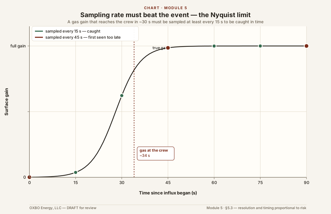
The third is that timeliness and sampling rate must match the risk. A measurement taken too seldom is blind to what happens between the readings. The governing rule is the Nyquist limit: to resolve an event, a measurement must be sampled at least twice as fast as the event develops. If a gas influx can reach the crew in thirty seconds, the volume and gas readings are taken at least every fifteen. Sampling at one-second intervals and faster is inexpensive technology now, so there is little excuse for sampling too slowly.
5.4 Mud Weight and Properties
The drilling fluid is the well’s primary barrier, and its condition is the first thing a crew measures. The single most important property is density, the mud weight, because it is the hydrostatic column that holds the formation back. A drop in mud weight is a loss of that barrier. Dilution reduces the column directly. Gas cutting the returns also lowers the measured density, though because the gas expands mostly near surface, it reduces the bottomhole pressure far less than the surface reading suggests.
Three simple field instruments cover most of what a geoexchange crew needs, and they are often sold together as a kit for a few hundred dollars or less. The mud balance measures density. It is a beam balance with a fixed-volume cup at one end and a sliding rider on a graduated arm. The cup is filled and leveled, the rider is moved until the beam balances, and the arm reads the weight directly in pounds per gallon. The Marsh funnel measures a working viscosity, the time in seconds for one quart to drain from a funnel of fixed dimensions, a fast field number that flags a fluid growing thicker or thinner. The sand content kit measures the abrasive solids that wear pumps and settle in the hole. A measured sample is washed through a 200-mesh screen, and the retained sand is read as a percent by volume in a graduated glass tube. These three are the critical set for geoexchange barrier management, and their proper use can be learned in days rather than months. The standard procedures for all of them are set out in API RP 13B-1, Field Testing Water-Based Drilling Fluids.
Where the risk warrants, the check extends further, to the gel strengths that govern how the fluid suspends cuttings and to the chemistry that reveals what has entered the system, most directly the chloride content that marks a saltwater or brine influx. This is the API mud check, a standard field routine, and it is a barrier test as much as a detection tool, confirming the barrier is intact and reporting the first evidence when it is not. Not every geoexchange bore will need fluid management at this level, and where it is needed the crew does not have to carry it alone. Vendors are available nearly everywhere to run these tests as a service and to supply the materials that adjust the properties they measure. Air and other gaseous fluids carry no such column, so where they are used this barrier and its check are absent, which is part of the added risk of air drilling in Section 4.9.
5.5 Volume Reconciliation

After the fluid itself, the most important measurement is volume, the reconciliation of what goes into the hole against what comes out. A well that returns more than is pumped is gaining, which is an influx. A well that returns less is losing to the formation. Not every rig carries a pit or tank system, and the purpose here is not to require one but to convey the principle and the practices behind it. The means are simplest to explain with tanks, and tanks are used to explain them here, but depending on the risk and the rig an equivalent and appropriate method can serve the same purpose. Where tanks are present, they are the basis of the volume measurement and are managed accordingly.
This step is a common source of serious error. A tank is a measurement only if its geometry is known and its level is read against a calibrated scale. Irregular pit shapes, unaccounted transfers, sloping bottoms, and eyeballed sight glasses turn a life-safety measurement into a guess. Careful tank metrology, knowing the barrels per inch of each tank, accounting for every transfer, and holding a stable baseline, is what makes a small gain visible while it is still small.
A return flow meter deserves caution. On larger rigs the flow paddle in the return line is an indicator, not a measurement. It reports a percentage of deflection rather than a volume, its response is nonlinear and saturates near full flow, where a gain would show, and it cannot on its own close the volume balance. True measurement of the flow leaving a well is genuinely difficult, because the returns are an abrasive, gas-cut slurry. A vortex meter erodes, and its shedding is defeated by two-phase flow. An ultrasonic meter loses its acoustic signal in the gas-cut, bubbly stream. A Coriolis meter is accurate on a clean single-phase fluid, but the returns are neither clean nor single-phase, so entrained gas degrades the reading, the pressure drop through it is high, and the cost is impractical for most of this work. The tanks remain the measurement, and a flow device, where one exists, is a fast indicator that prompts a check of the tanks.
5.6 Pump Rate and Pressure
Volume out is only half of the reconciliation. Volume in is metered at the pumps, and the pumps carry a pressure signal of their own. Fluid input is counted in strokes, and a stroke is a volume only if the pump’s true output per stroke is known. The theoretical displacement, the gallons per stroke, follows from the liner size and length, but no pump delivers all of it. Nearly every pump runs below its theoretical output even when new, and the actual fraction, the volumetric efficiency, depends on the fluid, the pump rate, and the condition of the valves and liners, among other things. It is not a fixed number to be assumed, and it is not only a matter of wear. The driller’s obligation is to reasonably know the efficiency of that pump under those conditions, because the strokes counted against it are the volume-in half of the reconciliation, and a wrong efficiency makes every gain and loss wrong with it.
Pump or standpipe pressure carries a second signal, one available even where no diverter or shut-in pressure exists. A change in pumping pressure at a steady rate can mark a change downhole. Pressure drops as lighter influx fluid lightens the column or the string U-tubes, and rises as the annulus loads or packs off. Rate and pressure are read together, because each explains the other.
5.7 Gas Monitoring
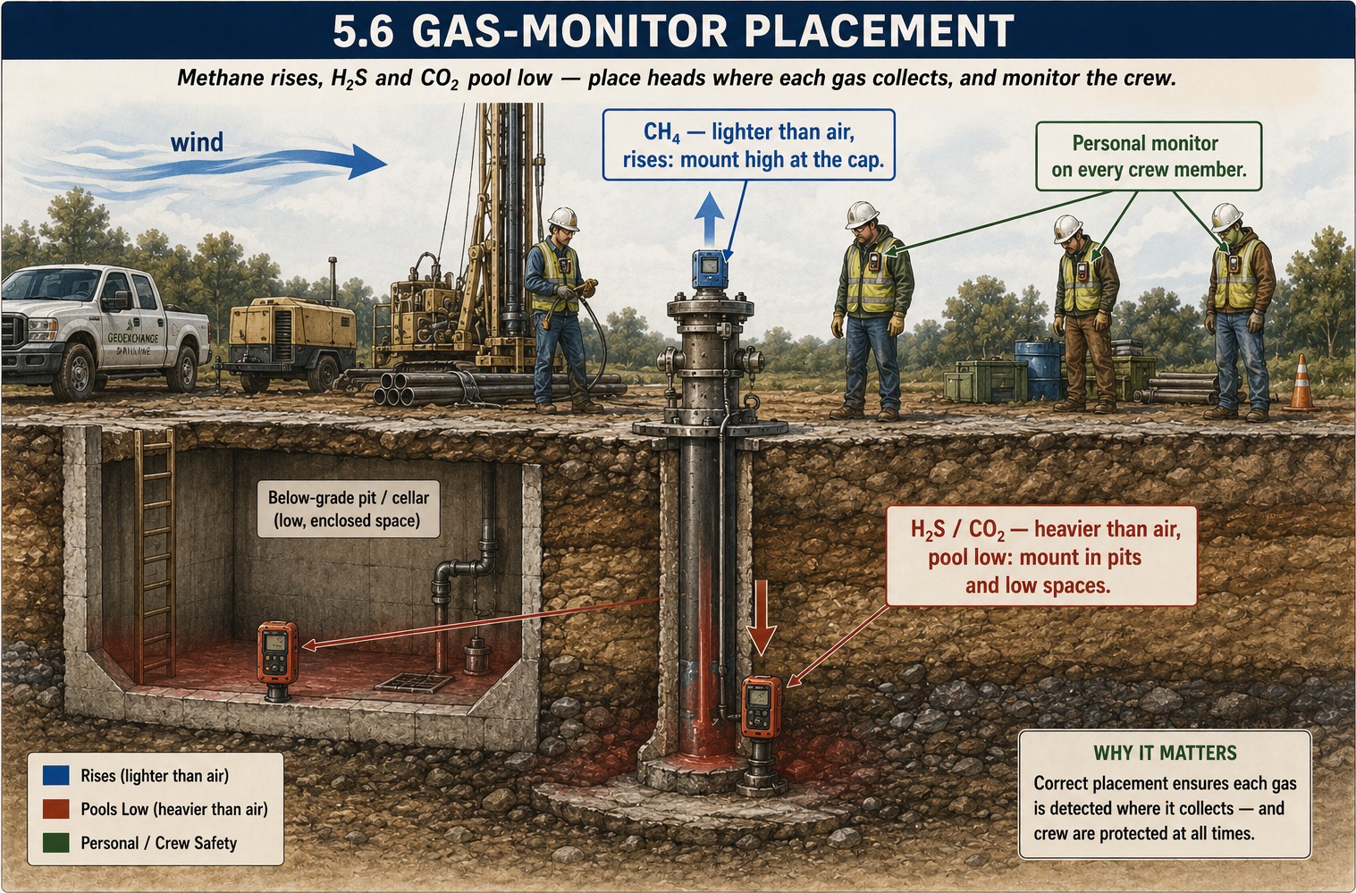
Gas in the returns is both a well-control signal and a life-safety one, and it is monitored for both. A combustible-gas detector reads the flammable fraction against the lower explosive limit, and a rise in background gas, or a surge on a connection or a trip, reports formation gas entering the fluid. Because the fluids of Module 3 include gases that harm before they burn, the monitoring cannot stop at the flammable range. A hydrogen-sulfide monitor is a life-safety instrument wherever a sour zone is credible, since the gas is lethal at concentrations far below anything a flammability meter registers and cannot be trusted to the nose. Oxygen and carbon-dioxide monitoring guards the low and enclosed spaces where a heavier gas collects.
Gas detection sits here, among the measurements, but its readings become indicators only when they are read in trend and in context, which is the work of the next section.
5.8 Pressure Sensors
Where the well can be closed, through a diverter routed to a manifold or a blowout preventer, the pressure it holds becomes a measurement. Shut-in pressures report the strength of an influx and the pressure the barrier must manage, and they are the input a control method in Module 6 works from. The qualification is that these readings exist only when there is something to close against. Much of the work this course addresses is drilled open to the atmosphere, on air or behind a diverter that vents rather than shuts in, and there a shut-in pressure is not available and the crew relies on the volume, fluid, and gas measurements above. A pressure sensor is a powerful tool where the well configuration provides one, and absent where it does not.
5.9 Vision-Based Systems
The newest additions to the toolset are cameras and machine-vision systems placed at the points a crew already watches: the return or discharge line, the shale shaker or cyclone, the blooey line, and the rig floor. They extend the driller’s eyes to places that are hard to watch continuously or unsafe to stand near, and some can flag a change in flow or level automatically. They are an aid to observation, not a replacement for it, and they inherit the same limit as the human eye, seeing the surface expression of an event rather than its downhole cause. Placed well, they lengthen the time a crew has to react by catching a change a busy driller might otherwise miss.
These are the instruments the crew has to work with, the driller foremost among them, and what they produce is raw measurement. The next section turns those measurements into indicators, the specific patterns of gain and loss, pressure, and gas that together tell a crew an influx is underway.
5.10 Overbalance and Buoyancy

Crews are taught to weight the drilling fluid to hold back gas, and they can see that the gas is lighter than the fluid. This raises a question that is seldom answered directly: if the gas is lighter, why does the fluid column contain it rather than let it rise out of the hole? Two separate mechanisms are involved, and they act along different axes.
Buoyancy is a vertical force. It governs how a low-density fluid behaves after it is already in the bore, where it rises. Overbalance governs a different quantity, which is whether formation fluid enters the bore at all. Formation fluid crosses the borehole wall only where the bore pressure at that depth is below the pore pressure in the rock. This flow is lateral, and the pressure difference drives it. The density of the gas does not determine whether it occurs. When the bore pressure equals or exceeds the pore pressure, the formation does not flow, regardless of the density of the gas.
The gas a bore encounters has already risen as far as buoyancy can carry it. Over geological time, gas that buoyancy could move through the rock has migrated upward and escaped. The gas that remains rose until a seal stopped it and has stood at that structural high since. The seal holds it through capillary entry pressure, the threshold that a gas column must exceed before it can enter the fine, water-wet pore throats of the sealing rock. A seal is therefore a pressure threshold. The traps and seals that hold gas in place are treated in Module 1.
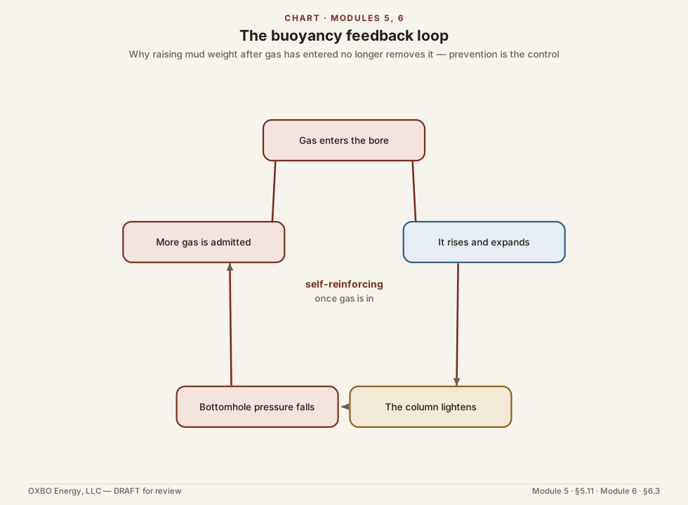
Drilling changes this condition. The bore is a new pathway that bypasses the seal, with negligible capillary resistance and a zone of lower pressure at its base. Whether the trapped gas flows into the bore depends on the direction of the pressure difference, and the fluid column holds the bore pressure above the pore pressure. After gas enters, buoyancy again becomes significant. The gas rises, expands, lightens the column, and lowers the bottomhole pressure, which admits more gas. This feedback, and the response to it, are treated in Module 6, which also explains why increasing the mud weight after gas has entered no longer removes it and why prevention is the remaining control.
Two qualifications apply, and both concern how the well is read. First, overbalance does not stop every gas return. Gas held in the rock that the bit cuts is released as the cuttings are made, so gas-cut mud can appear on a properly weighted and otherwise stable hole. Two errors follow: reading ordinary cuttings gas as a kick, and dismissing a genuine influx as cuttings gas. Separating the two is a question of trend and volume, treated in the indicator sections that follow. Second, overbalance is not a static property. A mud weight that is adequate on the report can be inadequate during a trip. Swabbing as the string is pulled lowers the pressure below the bit, and where that reduction falls below the pore pressure the formation flows even though the reported mud weight is correct. This is the condition behind the tripping and casing-running incidents in the record, in which the crew was moving pipe rather than making hole. It is treated with the other tripping indicators in Section 5.12.
5.11 Drilling Indicators
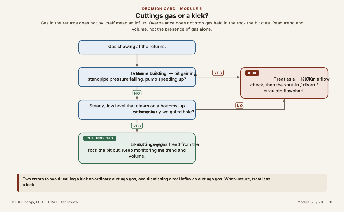
While the bit is turning and the well is circulating, the crew has the most to work with. The tools of the sections above are all live, and an influx or a loss leaves several marks at once. The indicators below are the ones that matter. No single one is trusted alone. The driller reads them together, in the pattern-recognition sense of Section 5.1.
Volume and Pump Pressure
The most direct indicator is a change in volume, and in one case a change in pump pressure leads it. The reconciliation of Section 5.5 exists to catch the volume, and a departure in either direction is bad news.
A loss, where less returns than is pumped, means the formation is taking fluid from the well. The barrier may be compromised. The fluid is leaving to a thief zone, a natural fracture, or a vug, and a hole that is losing its column can lose the very overbalance that holds an influx back. A loss is not only a lost-circulation problem to be cured. It is a warning that the pressure balance the crew is relying on may no longer be what they believe it to be. Where the loss comes from breaking down the rock, the pump pressure moves first and the change in return rate and volume follows immediately after, so the two are read as one event, the pressure noted first and the volume confirming it.
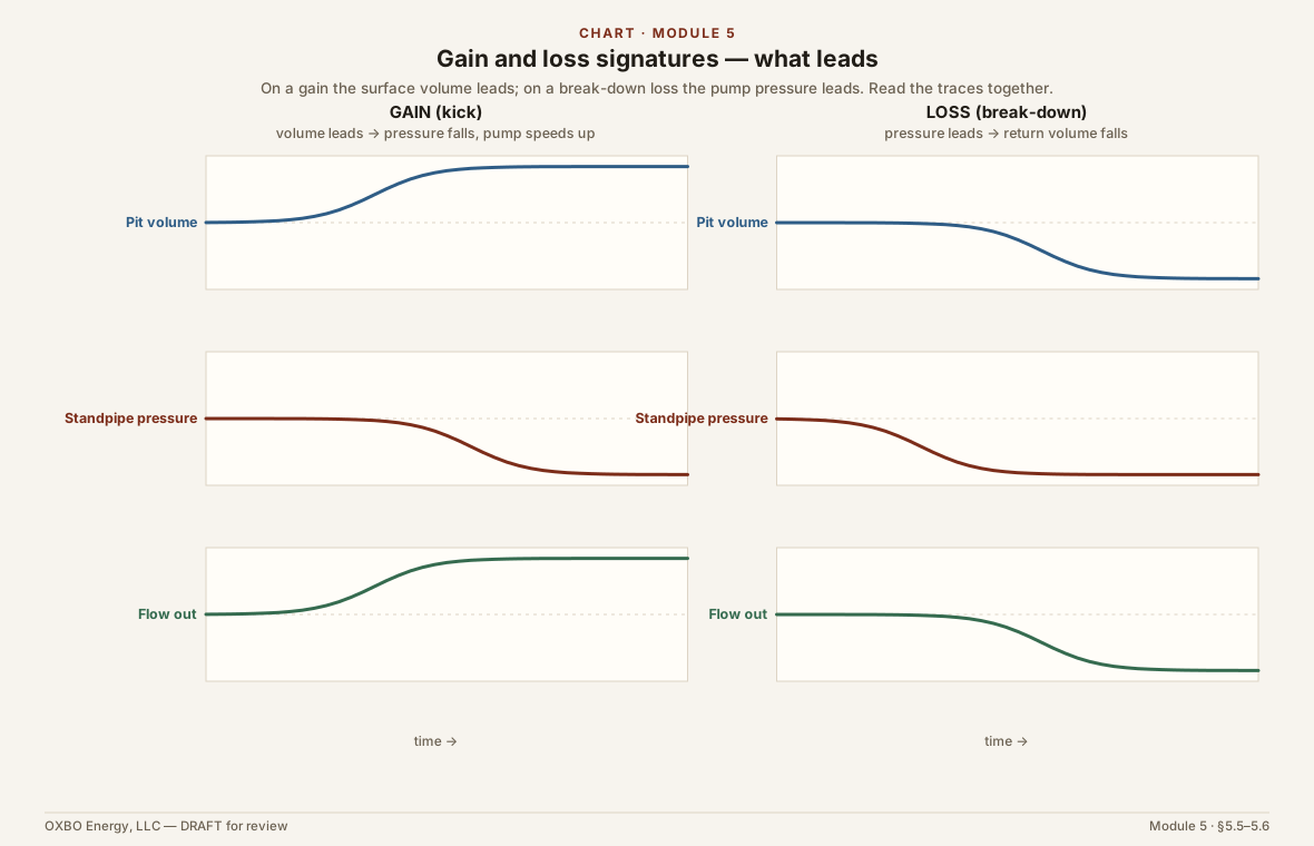
A gain, where more returns than is pumped, means the formation is giving fluid to the well. Here the barrier is compromised, not merely suspect. For a gain the volume leads. Flow out exceeds flow in and the surface volume rises, and only then does the standpipe pressure fall and the pump speed up at a constant throttle, as the lighter influx unloads the annulus. Something downhole is entering the bore and adding to the volume at surface, and until it is identified and controlled the well is taking a kick.
At the shallow depths of this work, a gas gain often shows at surface almost at once. Gas has little solubility in the fluid at these conditions, so it stays largely free and moves up the hole quickly rather than dissolving and hiding. A small influx arrives as small bubbles in the returns. A large one can eject a large volume from the bore almost instantly. Shallow wells have shown the whole range, from a faint stream of bubbles to a violent unloading, and the character of the flow changes with the amount of gas it carries.
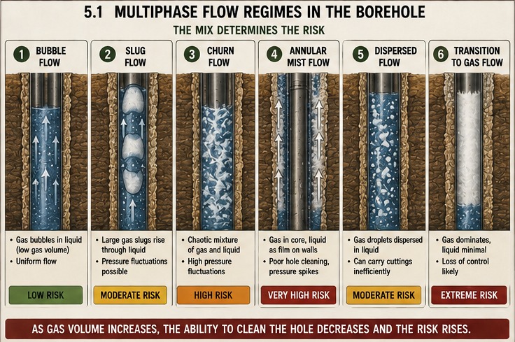
Because the gas is free and fast, a properly calibrated and well-placed gas detector, of the kind described in Section 5.7, should catch it quickly and reliably, and it is one of the fastest confirmations a crew has that a gain is gas. The volume system and the gas detector are read together. The volume says the well is gaining, and the gas reading says what the gain is made of.
The measurement that catches all of this is only as good as its resolution and its timing. A shallow gain develops fast, which is why the metrology of Section 5.3 requires the volume system to resolve a small change and to sample it often enough that the gain cannot pass unseen between readings.
Cuttings and Cavings
Gas in the returns may not be the first sign that pressure is trying to escape. The size and shape of the rock the bore returns can give an earlier one, where a shaker or a return sample lets the crew see it. Many geoexchange bores are drilled on air to a cyclone or a settling pit rather than a shaker, and there this indicator is read from whatever sample the returns allow. It is mostly a wellbore-stability signal, and wellbore stability is mostly a concern about getting stuck, losing tools, or losing the bore rather than about influx. One of its forms, though, carries a pressure story worth reading.
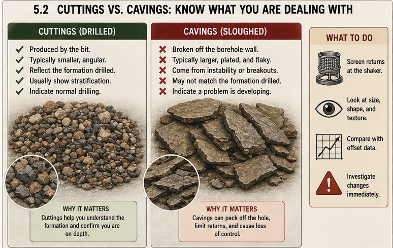
Rock grows stronger under confining pressure. Within the operating window, a wall supported by adequate fluid pressure fails only where the bit cuts it, and the cuttings it returns take their size and shape from the bit and the drilling parameters, an effect reinforced by chip hold-down, where the overbalance pins the cuttings against the bottom and grinds them finer. Lower the support toward the pore pressure and the near-wall rock begins to fail on its own and arrive as cavings, larger than and distinct from drilled cuttings.
Cavings come in three shapes, and each says something different. Splintery cavings, long and thin and concave, are the pressure sign. They form where the wall pressure has fallen below the pore pressure and the near-wall rock spalls as the pore fluid drives it off, and they indicate the well is at or past underbalance, with an influx possibly near. Angular, blocky cavings point to shear breakout, the rock failing because the fluid pressure is too low to support it against the in-situ stress. Tabular cavings come off natural bedding planes and say little about pressure. The volume tells as much as the shape. When more is crossing the shaker than the bit is making, the wall is contributing, and that excess is itself a warning.
The Drilling Break
The same rock strength that governs the cuttings governs the rate of penetration, and a sudden increase in that rate, a drilling break, is the same physics read through the bit. As the effective pressure supporting the rock falls, the overbalance dropping as the pore pressure rises, the rock’s confined compressive strength falls with it and the bit advances faster, an effect helped along as gas escapes and breaks up the newly cut formation and as the drop in overbalance releases the chip hold-down. A break can simply mark a softer bed, but it can also mark the pressure regime changing, the very transition that precedes an influx.
A sharp increase in penetration rate, a doubling or more, is a reason to stop and check the well rather than to press on, letting the volume and the flow settle out whether the faster drilling is only softer rock or the leading edge of a kick.
Sticking Pipe
The driller can feel a change in the hole before any gauge reports it, the haptic sensing of Section 5.1 at work. When it becomes hard to transfer weight to the bit, or the string comes back heavier than it should on the way out, the pipe may be sticking to the wall. The common mechanism is differential sticking, where the difference between the wellbore pressure and a permeable formation presses the string into the filter cake and holds it there. Read correctly, it signals two things. The well is overbalanced against that zone, which is reassuring from a kick standpoint, and it has met a permeable, cake-building formation. The fluid lost to build that cake is filtrate seeping into the rock, and it does not register as a gain or loss at the tank. This is a stuck-pipe and filtration signal, and it should not be read as lost circulation.
5.12 Indicators While Tripping and Running Casing
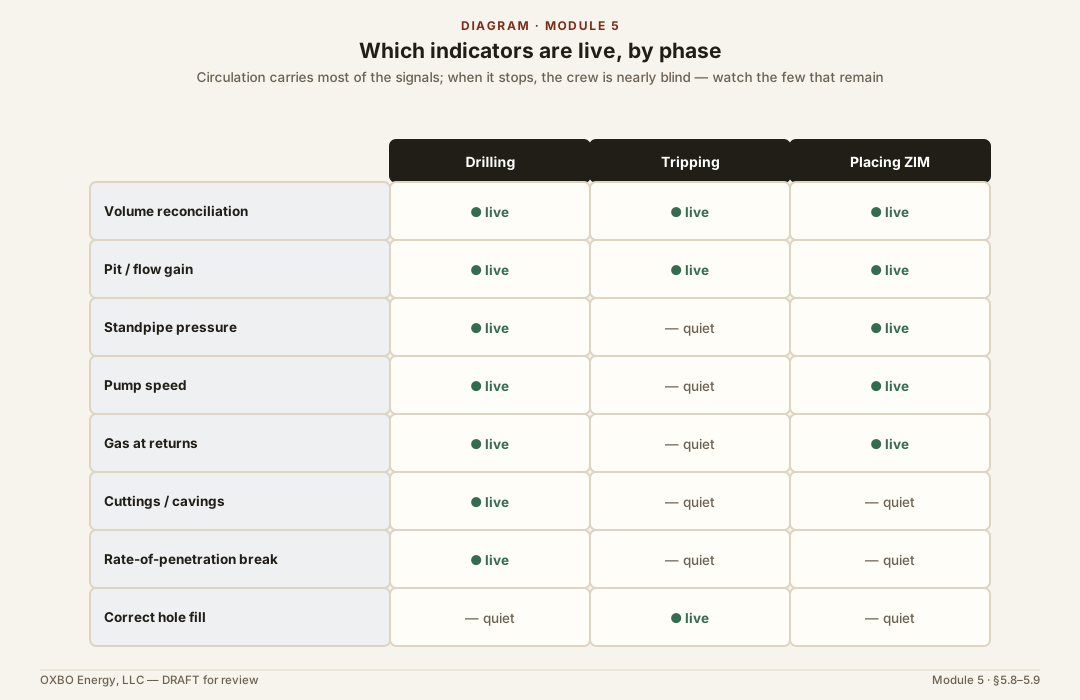
The worst well-control incidents happen while tripping pipe or running casing, and the reason is not that the indicators change. They are essentially the same indicators. What changes is that the information grows scarce and the observation grows critical. Circulation is stopped, so volume, gas, cuttings, pump pressure, and rate of penetration all fall quiet, and the crew is left with a few signals that must be watched far more closely, because an influx taken now, with the string out of the hole or the casing only part-way in, is far harder to control than one taken while drilling.
Two things carry the weight. The first is correct hole fill. As pipe is pulled, the hole must take fluid to replace the steel removed, and as pipe or casing is run, it must give back the fluid the steel displaces. Filling the annulus and the pipe by the book, and tracking the fill against the calculated volume of steel moved on a trip tank and a trip sheet, is what turns a hole that is not taking its proper fill into the early warning it is. A hole that will not take its calculated fill is swabbing, or already feeding an influx.
The second is surge and swab management. The operationally induced pressures of Module 2 run in both directions here. Pulling the string too fast swabs the well, lowering the pressure and drawing fluid in. Running too fast surges it, raising the pressure and risking a breakdown and a loss. Controlling the trip speed, and keeping the hole full while doing it, is the whole of prevention during these operations, because the tools that would catch a mistake after the fact are the ones that have gone quiet.
For the closed-loop geoexchange bore the analogous operation is inserting the loop, and it behaves differently from a steel string. The high-density polyethylene U-bend is light and buoyant, so it must be filled with water, and sometimes weighted, to reach bottom at all, and it is run in once rather than tripped in and out. Because the loop is slender and light, the surge and swab it induces are small next to those of a close-tolerance steel string, so the concern shifts from swab-induced influx toward keeping the hole full and watching the returns and the fluid level as the loop displaces its own volume on the way down. The tripping and casing cautions above apply in full to the water-well side of this work, where a steel string and casing are run.
5.13 Well Control During Zonal Isolation
Well control does not end when the hole reaches depth. It continues through the placement of the zonal isolation material, the grout, cement, resin, or foam that seals the bore, and the crew’s detection duty runs to the end of that pour. The barriers to this point have all been temporary, the fluid column, the diverter, and the crew’s attention. The zonal isolation material is the barrier that remains after the rig leaves, and confirming that it went where it was meant to is the last detection task on the well.
The surest confirmation is full returns to surface. In mineral wells, many regulators require either full returns or a log demonstrating a satisfactory top of cement; geothermal drillers, to the author’s knowledge, are generally held to neither. It is wise to require full returns anyway. It produces waste, but it is the most certain demonstration that the annulus is filled from bottom to top, and the returns must be read rather than merely observed. What comes back should match the density and composition of what was pumped, not flush water or a thinned and mixed slurry. If gas appears in the returns, or is seen migrating to surface through the grout, the isolation is already compromised, and remedial action, along with proper reporting to the engineer of record and the authority having jurisdiction, is required rather than optional.
Where full returns cannot be achieved, the top of the material is determined by appropriate means. If the material is not self-supporting, that top is measured at least twice, with enough time between the measurements to establish the rate of subsidence and leakoff, the same redundancy and timing discipline the metrology of Section 5.3 demands of every life-safety measurement.
Here detection hands off to design. Zonal isolation is the one form of well control that is permanent, the barrier that must still be holding after the crew has left the site, and how it is specified, placed, and kept sound over the operating life of the asset is the whole subject of Module 7. That module takes up the staged densities that hold the pressure window across every formation, the material behavior that governs top-off, a loop-pressure-testing hazard peculiar to closed-loop geoexchange that can set a leakage pathway into the finished seal, and the record of what a lost barrier does to the aquifers a bore crosses. What matters here, at the rig, is that the crew watches the pour to its end and reads the returns as the proof that the barrier is in place.
Key References
- American Petroleum Institute. API RP 13B-1, Field Testing Water-Based Drilling Fluids (the mud balance, Marsh funnel, and sand content test of Section 5.4).
- Kumar, D., Ansari, S. A., Wang, S., Ahmed, S., and Tichelaar, B. Real-time Wellbore Stability Analysis: An Observation from Cavings at Shale Shakers (2012), on reading cavings at the shaker and the association of splintery cavings with underbalance; the splintery, angular, and tabular taxonomy is standard in the wellbore-stability literature (Section 5.11).
- Operators Group for Data Quality, and the IADC drilling-metrology guidance and API metrology specifications informed by it (the measurement principles of Section 5.3; see Acknowledgements).
Acknowledgements
The measurement principles in Section 5.3 draw on the work of the Operators Group for Data Quality, an effort among more than twenty operating companies to define common specifications for the quality of drilling sensor data, including its accuracy, precision, trueness, sensitivity, fidelity, reliability, completeness, and timeliness. That work has since informed improved metrology guidance from the IADC and updated metrology specifications from the API. The principles restated in this module are a deliberately small subset of it, narrowed to the measurements on which well-control safety depends.
This module is © 2026 Nathan Zenero, OXBO Energy, LLC and is licensed under the Creative Commons Attribution-NonCommercial 4.0 International license (CC BY-NC 4.0), on the terms stated in Module 0. Requests for commercial licensing, submissions for the public errata, and accounts of encountered influx may be sent to nathan@oxbo.energy.