
Author: Nathan Zenero, OXBO Energy, LLC
Audience. Written for working geoexchange and water-well drillers and their crews, and for the contractors, design engineers, specifiers, and regulatory authorities who share responsibility for the boreholes they construct.
Zonal Isolation
Zonal isolation is a permanent form of well control. Every other barrier in this course acts only while the crew is on location. The isolation column acts for the life of the bore.
Its purpose is to isolate flow paths and to segregate fluids between zones. It is the most important duty the driller has to the public and the one that the AHJ will scrutinize the most.
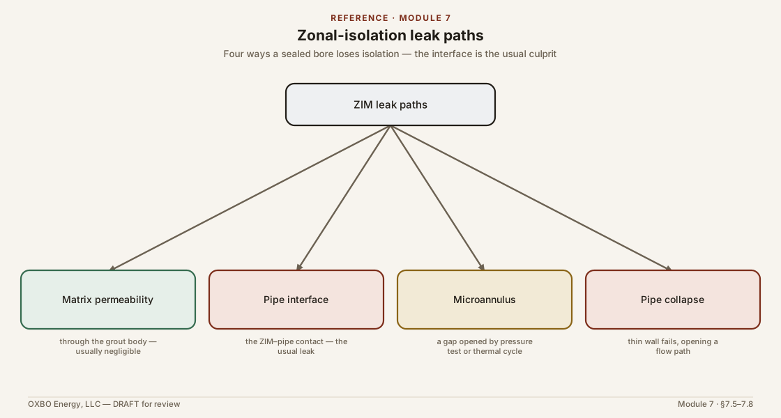
In addition to isolating the earth from the bore, zonal isolation must also preserve the geometry of and contact with the pipe(s) within the bore. A pipe that collapses opens a flow path. A microannulus created during pressure testing opens a flow path. Both are failures of well control.
The industry has noted these concerns in its own literature and has not resolved them. They are covered here because they bear on the only permanent barrier.
7.1 The Material and Its Names
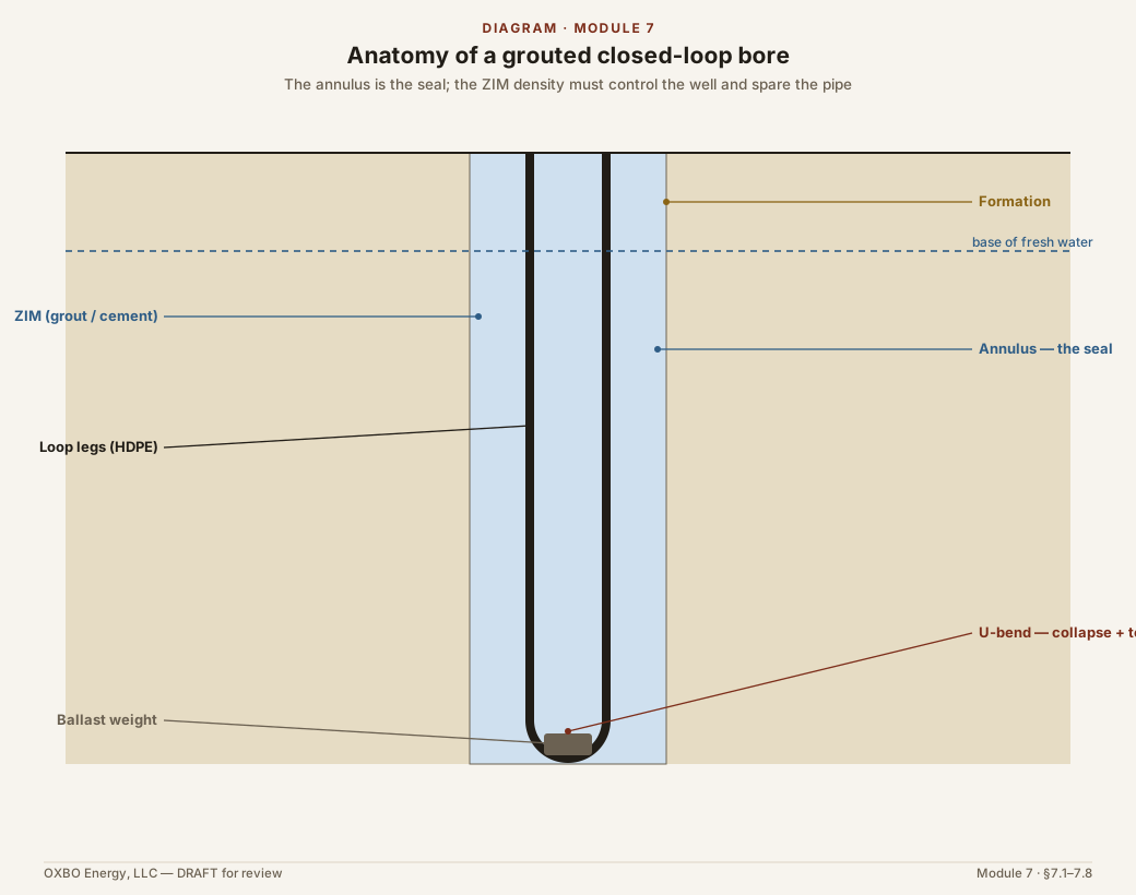
The zonal isolation material, or ZIM, is the material placed in the annulus, the space between the bore and any pipe(s) in the bore, to isolate the flow paths and prevent flow to surface or to other subsurface formations. ZIM can be grout, cement, foam, resin, or other material(s) so long as it has the permeability, pressure, temperature, and chemical resistance ratings required to prevent flow.
Grout is the most common material used in geoexchange bore construction and often the terms may be used interchangeably. Most grouts are either bentonitic or cementitious. Bentonitic ZIM is built on sodium bentonite, a clay that swells in water and seals by that swelling. Cementitious ZIM is built on Portland cement, which sets by hydration and seals by that set. The two behave differently. They have different pumping characteristics, cure differently (if at all), and fail differently.
A ZIM is specified for the fluids it will meet. The pore fluids of Module 3 are not inert. Brine, carbon dioxide, and hydrogen sulfide each attack some materials and leave others intact, and a ZIM that degrades in a fluid the bore crosses stops being a barrier where it is needed most. The engineer and/or AHJ should specify a ZIM that survives the fluids reasonably expected at the site. The chemistry of that degradation, and the selection of resistant blends, is a discipline of its own and lies outside the scope of this course. What belongs here is the requirement. The material must survive contact with those fluids.
ZIM is sometimes set in combination with downhole tools, the most common of which is the plug. A plug is a mechanical element set to hold a position in the bore. Plugs are most often used in abandonment of a bore and are a critical part of abandonment when used. Most AHJ have detailed requirements for the use of plugs. The specific placement and testing of a plug will be addressed in a future section on bore abandonment.
7.2 ZIM Specifications and Validation
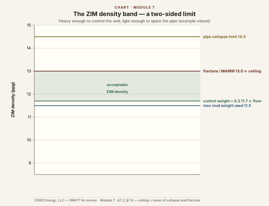
The most critical property of ZIM is its density. However, the most common, and oftentimes only, material property specified for ZIM is thermal conductivity. While this is clearly critical for thermal performance and economics, it has almost no bearing on zonal isolation.
Assuming the ZIM is sufficiently impermeable, the density of the material is the only factor that the driller can manage to ensure proper isolation.
Drillers should require a density specification for ZIM and should validate it against flow checks and other well control calculations during construction. Drillers should mix ZIM so that its density is at least the minimum mud weight (including ECD) required to control the well during construction plus an additional safety margin which is recommended to be at least 0.2 lb/gal and not exceeding the fracture gradient.
7.3 Placing the Column
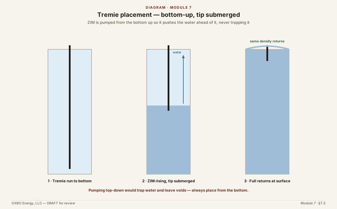
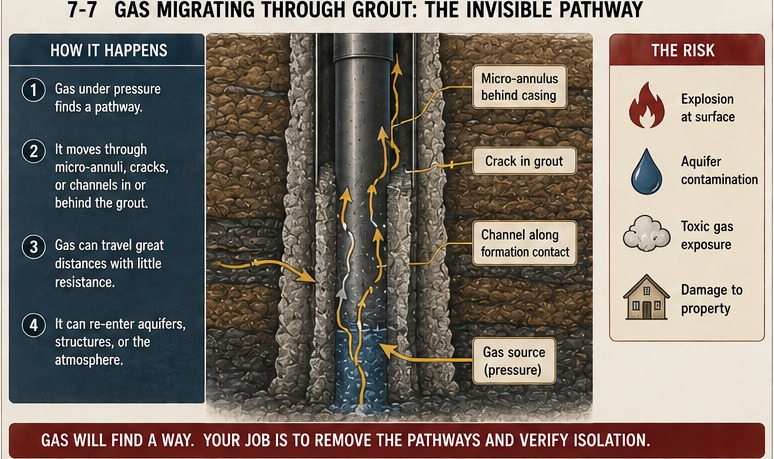
The ZIM is usually placed by tremie, from the bottom up. The tremie tip stays submerged in the ZIM as the level rises. Bottom-up placement pushes the water ahead of the ZIM and fills the annulus without trapping fluid. The ZIM cannot be circulated out once it is placed. Placement is the control, not recovery.
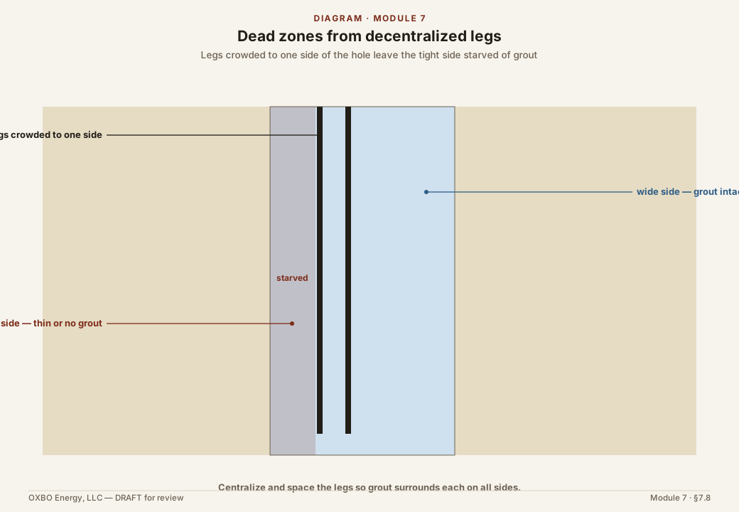
Even placement is difficult for two reasons. The annulus holds two pipe legs, and sometimes four or more, with a U-bend at the bottom. The legs are not centralized in common practice and can twist and touch. The hole is also rarely straight, because shallow bores are drilled by pushing the bit, and a spiraled hole varies the standoff around the pipe and along it. Both conditions leave narrow gaps where the ZIM may not reach. These are dead zones. Pumping in turbulent flow distributes the ZIM more evenly than laminar flow. Reciprocating the tremie, where the equipment allows, works the ZIM into the narrow gaps. Together they reduce the dead zones between the pipes.
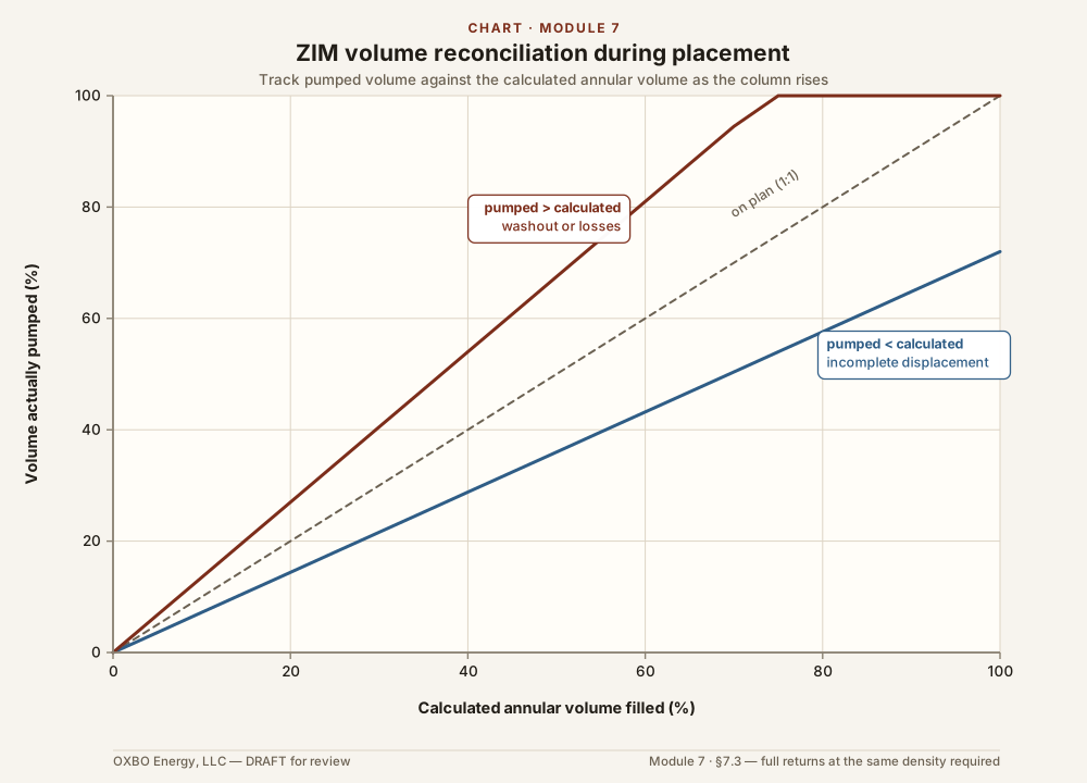
The ZIM is usually mixed in batches, and batches vary. Drillers should sample every batch. The ZIM density should be measured and recorded before that batch is pumped. The volume pumped should be reconciled against the calculated annular volume as the column rises. Pumping less than the calculated volume to reach surface is a sign of incomplete displacement of annular fluids. Pumping more is a sign of a washed-out hole or losses.
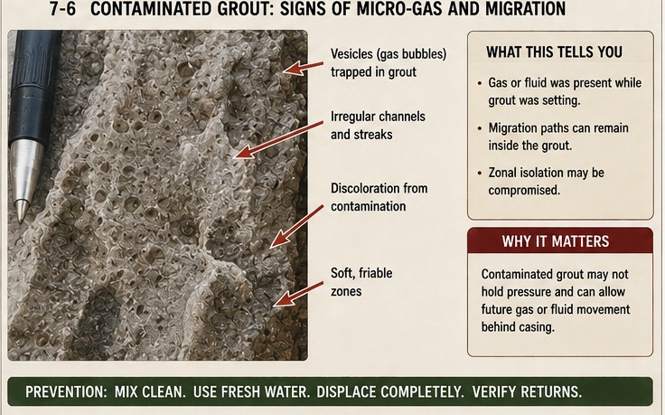
Full returns of ZIM to surface should be required. ZIM returned to surface should not be diluted and should be the same density as that which was pumped into the bore. Chlorides prevent proper hydration and performance of bentonite grouts and cements. ZIM that is contaminated with brine may never satisfy its design intent.
Many times, the ZIM in a bore subsides and requires a “top-off”. If subsidence occurs, it should not be assumed that subsidence is complete. The top of the ZIM should be measured twice, with enough time between the readings to confirm that the column has stopped subsiding. This confirms that a top-off will hold. The top of the ZIM should be recorded and reported for every bore, before and after each top-off. Top-off ZIM is measured and recorded the same way as the primary column.
7.4 Influx During Placement
There is no good answer to an influx during placement. The ZIM is placed by tremie and cannot be circulated out of the hole. A column of drilling fluid can be reconditioned, but a placed ZIM cannot.
If influx occurs, it should be monitored continuously. Any gas should be vented or flared. Any liquid influx that is expressed at the surface should be managed under the spill-control part of the emergency response plan. A well control specialist should be engaged when required. The specialist may recommend plugging and abandoning the bore, excavating around it, drilling a relief bore, or another measure. Once the ZIM has set, the options are few and suboptimal.
Control during isolation is therefore prevention, not recovery. The heavy ZIM of Section 7.2 holds the formation while the column is fluid. The placement practice of Section 7.3 keeps the column continuous. A bore with active flow before grouting is not ready to grout, because a tremied column may not overcome the flow. The flow is controlled first.
7.5 The Grout–Pipe Interface
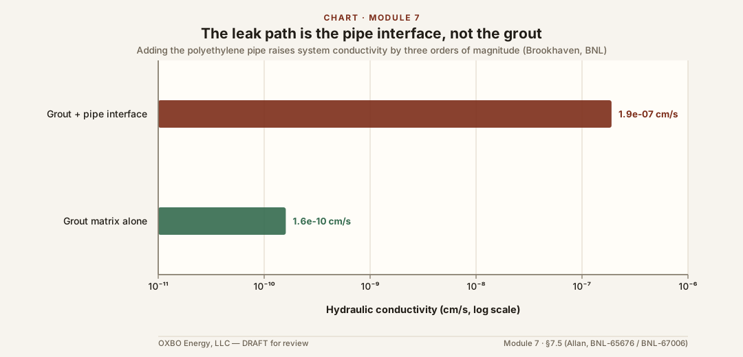
The leak path in a closed-loop bore is usually the interface between the ZIM and the pipe, not through the matrix of the ZIM itself. Brookhaven National Laboratory measured this for the U.S. Department of Energy in the late 1990s. The grout alone had a hydraulic conductivity near 1.6 × 10⁻¹⁰ cm/s. The grout with the polyethylene pipe included rose to about 1.9 × 10⁻⁷ cm/s. That is three orders of magnitude. The interface controls the permeability of the system.
The bond at the interface is mechanical friction. It was measured by a push-out test. Polyethylene is nonpolar and does not chemically bond to cement or bentonite. A small change in the fit of the pipe opens a path along it.
Common causes for separation of pipe and ZIM are seismicity and deformation. Because HDPE is viscoelastic, its geometry can change over time with acute and chronic stresses and temperature changes.
Zonal isolation materials that are designed to never achieve a self-supporting matrix affect isolation in two ways. If the pipe is viscoelastic and the hydrostatic differential from the ZIM and the operating pressure in the pipe is high enough, the pipe can “creep” and slowly collapse over time. Thus, it is critical for the engineer to specify pipe with sufficient rigidity (from both materials and dimensions) to resist these effects for the life of the bore. It should be noted that many HDPE and other pipe manufacturers do not publish collapse ratings because the standards bodies do not consider them structural members and only require their burst ratings be known.
7.6 The Microannulus from Pressure Testing
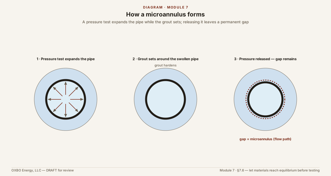
Zonal isolation materials that are designed to be self-supporting generally require a curing period to achieve their designed material properties. During the curing period, these materials may behave in non-plastic regimes and have different failure modes than when they are cured. Many cements develop a “gel strength” before they are fully cured. During this phase, the material can be deformed and may hold its deformed shape. This is critical when performing pressure tests for quality control and submittals to the engineer of record or the AHJ.
The pressure test is generally specified as 1.5x the maximum designed operating pressure. Elastic pipes, like HDPE, can expand enough to create a permanent microannulus between the pipe and the ZIM. Even a temporary microannulus can be infiltrated by formation fluids, which can cause the annulus to remain open even after the pressure is removed and the pipe and ZIM are in their relaxed steady-state condition.
Drillers should observe samples taken from the ZIM installation and should not pressure test material in a manner that is likely to create a microannulus. That is, if the material demonstrates properties that suggest it will deform significantly during pressure testing.
7.7 Thermal Debonding
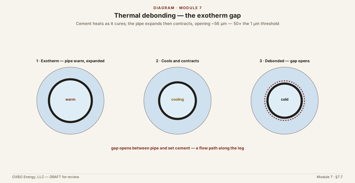
The ZIM also separates from the pipe when the temperature changes. Cement gives off heat as it hydrates. The pipe warms and expands during placement, then cools and contracts. With a circumferential expansion coefficient of 1.1 × 10⁻⁴ per degree Celsius, the computed diameter change from the exotherm is about 56 microns. That is more than fifty times the one-micron threshold.
Operation then works the gap each year. Fluid near 30 to 35 °F contracts the pipe and opens the interface. Fluid near 85 to 95 °F expands it and closes it. The gap opens and closes for the life of the field.
Drillers should allow all materials (pipe and ZIM) sufficient time to reach thermal equilibrium before pressure testing.
7.8 Collapse and Combined Loading
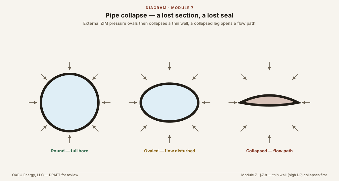
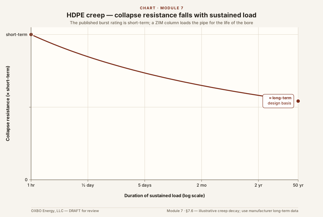
During grouting the pipe carries a net external pressure. The ZIM is heavier than the water inside the pipe, and no surface pressure counters it. The differential is zero at the collar and grows with depth. For a ZIM near 11.5 lb/gal it reaches about 260 psi at 1,600 feet. A heavier silica ZIM reaches more. This is the largest structural load of the pipe’s life.
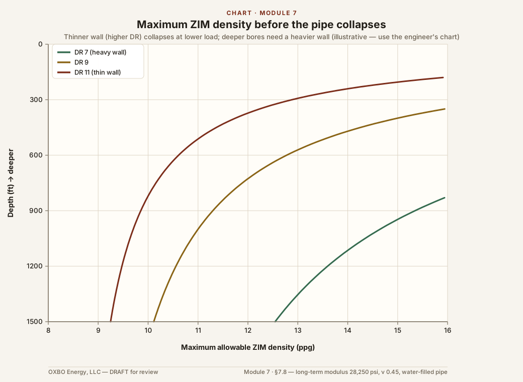
Thin-wall pipe resists collapse poorly. The dimension ratio is the outside diameter divided by the wall thickness. A high ratio such as DR11 collapses at a low external pressure. A collapsed pipe loses its round section, disturbs the column around it, and loses the seal along it. Collapse opens a flow path. Collapse resistance rises steeply as the wall thickens, so at depth only a heavy wall such as DR7 keeps margin. The pipe wall is therefore chosen to survive the ZIM weight at its depth.
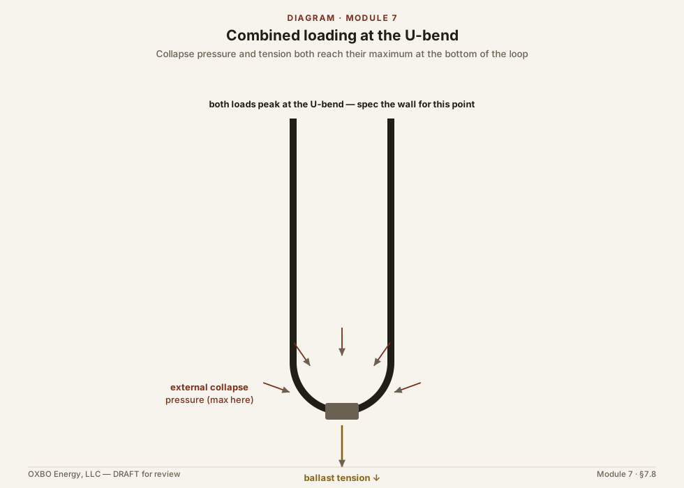
External pressure is not the only load. The loop is buoyant in the ZIM and will not stay down, so ballast is hung at the U-bend. The ballast puts the deep pipe in axial tension. The axial tension and the external pressure are both greatest at the U-bend. The combined stress there is high. Order-of-magnitude estimates place it near twice the long-term design stress of the material.
Density works against the pipe in both loads. A heavier ZIM raises the buoyant uplift, which raises the ballast and the tension. It also raises the external differential, which raises the collapse load.
Engineers should provide a collapse rating chart to the driller before ZIM is installed to ensure that the required ZIM does not present a collapse risk. This should include a maximum allowable ZIM density. Drillers should not exceed this density. If ZIM density required for zonal isolation cannot be achieved without a collapse risk, consider reducing the depth of the bore and setting pipe shallower or using pipe(s) of different materials that can withstand the combined loading scenario.
7.9 The Invasion Window
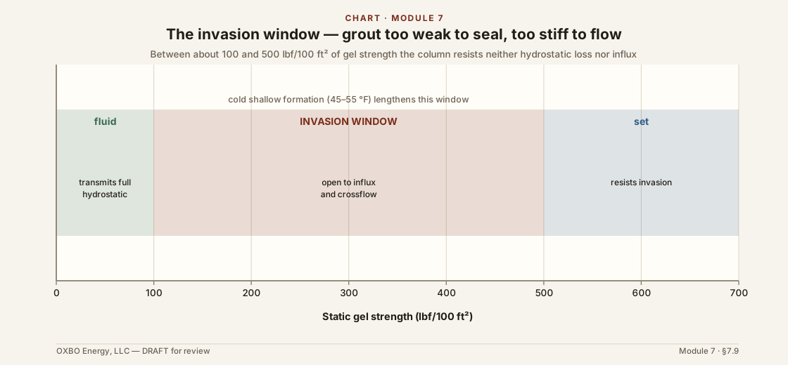
A ZIM column does not resist flow until it develops strength. While it is fluid it transmits its own hydrostatic pressure. As it gels it passes through a transition. During the transition it can neither transmit full hydrostatic pressure nor resist the entry of formation fluid. The petroleum literature places this window between about 100 and 500 lbf/100 ft² of static gel strength. A short window is safer. A long one leaves the bore open to influx and to crossflow between zones.
Cold formation lengthens the window. Geoexchange ZIM cures against shallow formation near 45 to 55 °F. Low-temperature hydration is slower and less complete. A bentonite ZIM with no accelerator can stay in transition for hours. A ZIM specified to remain plastic for the life of the system never leaves the transition. It never reaches the strength that resists invasion.
7.10 Case Histories
Failures of zonal isolation are documented in several settings. A Class VI carbon-dioxide storage well at Decatur, Illinois leaked along a corroded monitoring well, and the leak went unreported for months. Brine reached fresh aquifers along well paths near Brookhaven, Mississippi. Over-pumping near Roswell, New Mexico drew brine into fresh water. None of these is a closed-loop bore. Each shows why the annulus must keep the zones apart.
Closed-loop failures are on record as well. In the Czech Republic, completed geoexchange bores produced artesian overflow along the borehole. The overflow was stopped by perforating one loop leg and grouting through it. At Staufen im Breisgau, in Germany, closed-loop bores let water into an anhydrite layer. The anhydrite grew into gypsum and heaved the town center, damaging hundreds of buildings. The same happened to a single home at Lochwiller, in France. None was a pipe rupture. Each was a column that failed to keep the zones apart.
Key References
Allan, M. L. Geothermal Heat Pump Grouting Materials. Brookhaven National Laboratory, BNL-65676.
Allan, M. L., and Philippacopoulos, A. J. Properties and Performance of Cement-Based Grouts for Geothermal Heat Pump Applications. Brookhaven National Laboratory, BNL-67006.
Allan, M. L., and Philippacopoulos, A. J. Materials characterization of superplasticized cement–sand grout. Cement and Concrete Research, 2000.
Feneuil, B., et al. In-Situ Evaluation of Casing–Cement Debonding During Cooling. SPE/IADC 25DC, 2025.
Microannulus. ScienceDirect Topics, Engineering.
Buckling failure numerical analysis of HDPE pipes used for trenchless rehabilitation. Engineering Failure Analysis, 2013.
McLean, R. H., Manry, C. W., and Whitaker, W. W. Displacement mechanics in primary cementing. Journal of Petroleum Technology 19(2), 1967.
Isolating Potential Flow Zones During Well Construction. API Standard 65-2.
Methods of grout quality measurement in borehole exchangers for heat pumps and their rehabilitation. Geothermal Energy, 2024.
Best Practices for Geothermal Vertical Closed-Loop Installations. Michigan Department of Environment, Great Lakes, and Energy.
Suggested Specifications — Grouting Materials for Ground-Loop Heat Exchangers. GeoPro, Inc.
Proffer, T. HDPE Pipe Integrity at Depth: Vertical Closed Loop Ground Heat Exchangers. NY-GEO Conference, 2023.
This module is © 2026 Nathan Zenero, OXBO Energy, LLC and is licensed under the Creative Commons Attribution-NonCommercial 4.0 International license (CC BY-NC 4.0), on the terms stated in Module 0. Requests for commercial licensing, submissions for the public errata, and accounts of encountered influx may be sent to nathan@oxbo.energy.