
Author: Nathan Zenero, OXBO Energy, LLC
Audience. Written for working geoexchange and water-well drillers and their crews, and for the contractors, design engineers, specifiers, and regulatory authorities who share responsibility for the boreholes they construct.
The Desk Study
Who bears the risk of a closed-loop bore is often unsettled before the work begins, and two ambiguities decide it. The first is legal classification. A jurisdiction may regulate a closed-loop bore under its water-well code, name it a well of another kind, or reach it under oil-and-gas rules once it passes a set depth, and each classification carries a different construction standard and a different measure of the care owed. The same bore, drilled across a state line, can answer to a different body of law. The second is the division of design and contract. On a small residential loop the driller commonly sets the depth and the method and holds the risk that follows. On a large institutional borefield an engineer of record specifies the depth and answers to the owner, and the driller executes to that specification. Between these, the duty to know what the ground holds is assigned unevenly or not at all, and when a bore penetrates a hazard no one anticipated, the exposure settles on whichever party failed to look.
The desk study is how that exposure is moved from unmanaged to planned. Run before the bit turns, from public records and maps, it determines which of the hazards the earlier modules described apply to a specific site and plans the mitigation for each. Module 1 set out the pressures that can be identified before spudding, Module 2 the pressures the operation induces, and Module 3 the fluids an influx delivers and the harm they carry. Each of those modules ended at the same handoff. The desk study finds the conditions, and this module is that instrument, so that the crew meets the ground prepared rather than surprised.
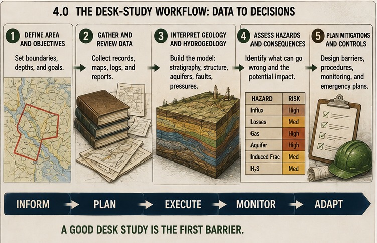
The rigor of the desk study is proportional to the risk. A shallow residential loop in well-characterized ground warrants a lighter study than a deep institutional borefield near known hazards, and the effort scales to the exposure. This course does not set a minimum level of rigor, because setting that floor is the prerogative of the authority having jurisdiction alone. What it recommends is that the parties who price and bear the exposure, the risk managers and the insurers, become closely familiar with how subsurface risk is assessed, documented, and disseminated, because their fluency is what makes the document a control on risk rather than a formality.
A Note on Shared Responsibility
Identifying a site’s hazards is a shared and defined duty. It is properly led by the design engineer and the authority having jurisdiction, who command the records, the permits, the specifying authority, and the power to require a mitigation, while the driller contributes local knowledge of what nearby holes have found and acts on the result at the rig. None of the parties discharges it alone. In much of this work, however, no engineer is engaged and the authority asks little, and the whole task lands on the driller by default, which is a gap in how the duty is assigned rather than a sound division of it. This module is written for both cases. Its products are built so that a driller can produce them alone, and they serve an engineer building a specification as readily as a driller working a site without one. A bore-construction standard would make the identification a required and assigned step rather than a matter of goodwill.
Module Structure
- Section 4.1 defines the desk study, its three products, and its limits.
- Section 4.2 sets out the records that feed it and what gives each its weight.
- Section 4.3 assesses the site for the pressure sources of Modules 1 and 2.
- Section 4.4 assesses the site for the influx fluids of Module 3.
- Section 4.5 builds the offset-well inventory and the cross-section.
- Section 4.6 assembles the geologic prognosis.
- Section 4.7 runs the area assessment, the proximity checks with defined radii.
- Section 4.8 plans the mitigation for each identified hazard.
- Section 4.9 addresses air drilling and the limits of the diverter.
- Section 4.10 covers the authority having jurisdiction.
- Section 4.11 covers the emergency-response plan.
- Section 4.12 addresses insurance and the well-control peril.
- Section 4.13 assembles the one-page risk sheet and the boundaries with adjacent modules.
4.1 The Desk Study: Purpose and Product
The desk study is a risk assessment run from records and maps before the rig mobilizes, and its purpose is to convert what is knowable about a site into a plan the crew can act on. It produces three linked documents. The geologic prognosis is a formation-by-formation forecast of the column the bore will drill, with the fluids and pressures expected in each bed. The offset-well inventory and cross-section place the nearby wells around the site and use their logs to build a picture of the section in every direction. The area assessment checks the ground within stated distances of the site for the conditions that a map at the bore alone would miss.
The desk study forecasts, and a forecast is not a guarantee. It narrows the range of what the bore may encounter and sizes the response to that range, but the ground can still differ from the record, and the detection and control of Modules 5 and 6 exist because the assessment can be wrong. The desk study lowers the probability of surprise and raises the readiness for it. It does not replace the barrier at the rig.
4.2 The Records the Desk Study Draws On
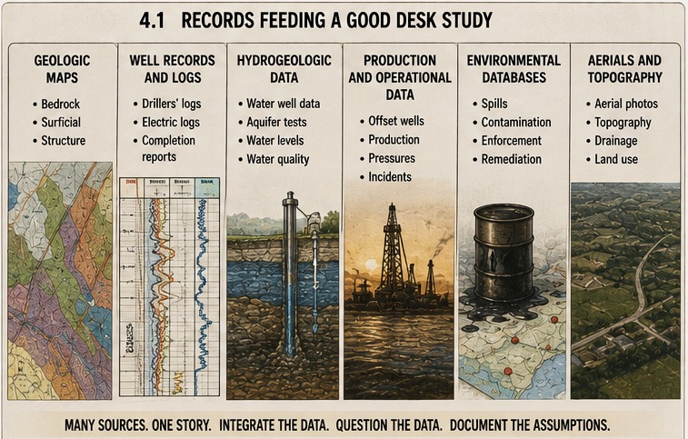
A desk study can most often be completed using only publicly available information, and it draws on a common set of sources.
- The state geological survey holds the bedrock and surficial geology, the stratigraphic columns, and the mapped occurrence of salt, coal, evaporites, faults, and organic-rich shale.
- The oil, gas, and mineral well database holds the logs and completion records of energy and mineral wells.
- The underground injection record holds the location, class, and pressure of injection wells.
- The water-well and groundwater database holds the driller’s records of nearby water wells, including depths, yields, static and artesian levels, and reported gas or salinity.
- The abandoned-mine and mine-void record holds the workings that store water and gas and that can transmit pressure.
- The solid-waste and landfill record holds the sites whose gas and leachate a bore must not connect.
- The environmental-remediation and contaminated-sites record holds the known plumes, the Superfund sites, and the prohibition and wellhead-protection zones that can bar or constrain a site.
- The authority having jurisdiction holds the permit conditions, the construction and sealing rules, the flowing-well rules, the setbacks, and the reporting requirements, and it is queried directly rather than only read.
The records do not all carry the same weight, and the difference is one of provenance rather than of any ranking the desk study assigns. A mineral well log is generally of higher quality than the others, because of how it came to exist: it was documented by a specialized geologist, paired with geophysical logs, often curated and approved by the authority having jurisdiction, and produced where the economics and the safety of an energy or mineral venture justified the cost of characterizing the ground precisely. That same logic of risk and economics explains the rest. An Underground Injection Control Class VI record, for the geologic sequestration of carbon dioxide, is produced under one of the program’s most demanding characterization requirements, a full area-of-review study with geophysical logs, and where one exists it is a first-rate preview of the deep section. A record made under a still stricter obligation would be more thorough again, as a repository for nuclear waste is modeled and monitored well beyond anything an injection well requires. A Class V record, the program’s broad category, is more variable, but it captures the geothermal-injection and aquifer-storage wells that are direct analogs and doubles as an induced-pressure flag. A water-well log is the most common record and the least standardized, and it is the shallowest, rarely reaching below the base of fresh water, which is the very interval geoexchange now enters. Below that depth the mineral, Class VI, and useful Class V records are frequently the only preview there is, and a careful assessment reads them for what the water-well record cannot show. A reader can confirm this difference directly by pulling a mineral well log and a nearby water-well record from the same area and comparing what each documents, and to what depth.
These records are cataloged for every state in the course’s companion, the Desk-Study Directory (reproduced in full in Appendix A), which lists the portals above alongside the federal resources and a crosswalk tying each Module 1 pressure source to the record that reveals it. The durable key in the directory is the name of the agency, because the agency outlasts the web address. The directory is a seed, extended as the work reaches jurisdictions beyond the fifty states, among them the Canadian provinces whose records and requirements Module 3 has already drawn on.
4.3 Assessing the Pressure Sources
Pressure sources described in Modules 1 and 2 should be identified and described as part of the risk assessment.
Natural pressure. The assessment weighs whether the section holds a confined aquifer under head, which raises the prospect of artesian flow, and whether the regional geology supports over-pressure or a subnormal, loss-prone zone. The survey and the water-well records carry the evidence, the latter often reporting artesian conditions in nearby holes directly.
Anthropogenic pressure. The assessment checks the Module 1 sources a study can find: injection and disposal wells that raise the local pressure, gas-storage fields, producing and legacy wells that tap or leak pressured zones, mine voids that store water and gas, and landfills that generate gas.
Ground prone to induced pressure. The operationally induced pressures of Module 2 cannot be forecast as events, because the operation makes them, but their preconditions can be flagged: weak or unstable formations, a narrow margin between the pore and fracture pressures, reactive or soluble beds, and faulted or fractured strata in the planned path that would give surge, swab, or circulation little tolerance.
4.4 Assessing the Influx Fluids
Influx fluids described in Module 3 should be identified and described as part of the risk assessment. Each fluid has a signature in the record.
- Gas is anticipated where the section holds glacial drift, coal, or organic-rich shale, and where nearby water wells report gas.
- Hydrogen sulfide is anticipated where the section holds evaporites, sour carbonates, or organic-rich shale, and where any nearby well reports a sour or sulfur show.
- Carbon dioxide is anticipated in carbonate sequences, in volcanic and geothermal ground, and along fault zones that tap deep gas.
- Petroleum is anticipated near legacy oil and gas fields, in shallow oil-bearing sands, at mapped seeps, and wherever an offset mineral well log records an oil or gas show, even one logged as non-commercial, because a show marks hydrocarbons the bore can encounter whether or not they were worth producing.
- Brine is anticipated near salt and evaporite beds, its concentration tracking the proximity to bedded salt, and reported salty or brackish water in nearby wells confirms it.
- Naturally occurring radioactive material is anticipated where the section holds uraniferous black shale, which carries the radon and radium of Module 3.
- A contaminant plume is checked against the environmental-remediation record, because a bore must not cross or spread a known plume, and a prohibition zone may bar the site outright.
4.5 Offset Wells and the Cross-Section
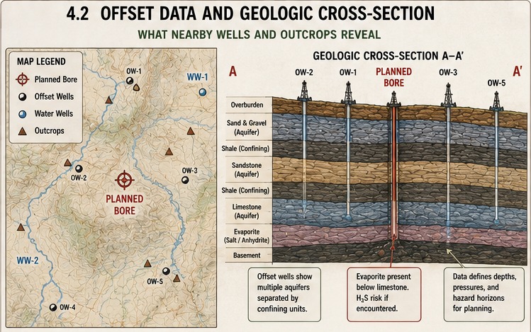
The single most informative source in a desk study is the record of the wells already drilled near the site. An offset well is a nearby hole whose log shows what the ground actually held, at what depth, and under what conditions, and a set of offsets around a planned bore is the closest thing to a preview the study can obtain. The inventory records each offset by its identity, type, direction, distance, and the logs available, so that the quality and the coverage of the evidence are visible at a glance.
| Well Identifier | Well Type | Distance from Site | Azimuth | Surface Elevation | True Vertical Depth | Records Reviewed |
|---|---|---|---|---|---|---|
| API no., EPA no., state ID, or well name | water, mineral, Class V, Class VI, or other | to the bore | ° from north | tie for correlation | of the well | driller log, geophysical log, geologist’s log, mud log, fluid analysis |
Surface elevation is what ties the formation tops together, because a top is only correlated between wells when each is referenced to a common datum. Without the elevations the tops cannot be lined up and the cross-section cannot be drawn.
Offset wells should be selected to form cross-sections that avoid bias in any one direction. A worked cross-section appears in Appendix B. Geostatistical or other spatial mathematical techniques can be used to better predict the properties at the location of interest.
A well’s reported status — producing, inactive, or abandoned — should not exclude it from the analysis. A bore recorded as abandoned regularly retains significant pressure, and the widespread problem of orphaned and “zombie” wells, some listed as properly plugged yet found leaking or blowing out, shows that a plugging record is not proof of a seal. An old or abandoned offset is a suspected conduit, the mechanism of Module 3, and is treated as one whatever its record says.
4.6 The Geologic Prognosis
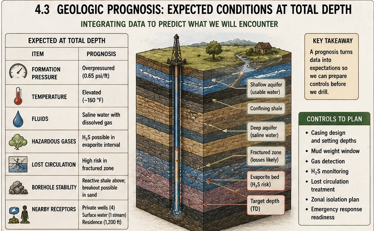
A geologic prognosis is a prediction or estimation of the geologic properties of the earth through which a bore will be drilled. It can be used for drilling performance, bit and tool selection, and cost estimation; for this course we focus on well control.
| Top (TVD) | Formation Name | Rock Type | Water Salinity | Oil Fraction | CH₄ (Y/N) | CO₂ (Y/N) | H₂S (Y/N) | Porosity | Permeability | Pore Pressure Gradient | Fracture Pressure Gradient | Other Hazards |
|---|
These geologic properties are necessary to understand the fluids that are present, their ability to flow, and the drilling mitigations that could be employed during a well-control event. They are not exhaustive, and additional information can be synthesized proportional to the risk.
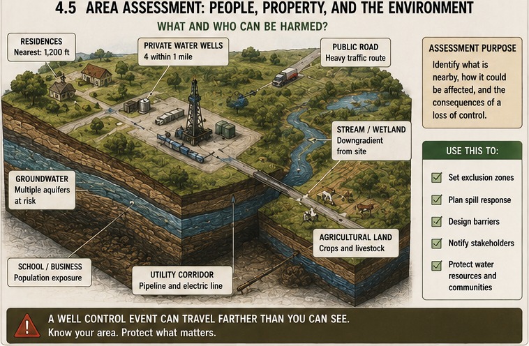
4.7 The Area Assessment
Due diligence demands a study of the area and transparency as to whether critical data was included. Analyzing a single mineral well may be insufficient if dozens are available for analysis. Additional risks must also be analyzed as shown in the following table.
| Trigger | Radius | Source | What it flags |
|---|---|---|---|
| Count of Class V and Class VI injection wells | 5 miles | injection record | induced pressure; Class VI is also superior deep data |
| Landfills | 5 miles | solid-waste record | gas and leachate; cross-connection |
| Reported gas in water wells | 1 mile | water-well database | shallow gas and methane |
| Reported hydrogen sulfide or brine in water wells | 1 mile | water-well database | sour or saline ground |
| Known artesian flow | area | water-well database, survey | high head; flowing-well control |
| Faulted, fractured, or karst strata in the planned path | path | geological survey | migration conduits; lost circulation; CO₂ |
| Base of fresh water | site | survey, offsets | isolation point; limit of water-well data |
| Known aquifer contamination, plume, or prohibition zone | any extent reaching the site | remediation and Superfund records | siting bar; cross-connection (as at Washtenaw County) |
| Distance to nearest navigable water | distance | hydrography, maps | Clean Water Act jurisdiction; spill reporting |
| Distance to nearest fresh-water body | distance | maps | severity of a release reaching it |
| Distance to nearest public-water intake or source-water protection area | distance | drinking-water record | setback; drinking-water reporting |
| Distance to nearest mine, and workings under the path | distance and path | abandoned-mine record | voids, mine gas, subsidence, acid drainage |
| Seismic hazard, with induced potential and active faults | site | USGS hazard model, ASCE 7 | integrity over asset life; fault reactivation |
| Distance to nearest important building or occupied structure, and to any below-grade or enclosed space near it | recommended standoff (Section 4.7.1) | maps, site plan, the authority’s setbacks | gas migration and accumulation in an occupied structure; building setback |
The distances to navigable and other waters mirror the logic of federal spill planning. The Spill Prevention, Control, and Countermeasure rule (40 CFR 112) governs onshore oil drilling and workover facilities directly and turns on the same question the area assessment asks — whether a site has a reasonable expectation of discharging oil to navigable waters, judged by proximity to water, land contour, and drainage — and it already anticipates a loss of well control by requiring a blowout-prevention assembly rated to the well-head pressure encountered. A significant influx can release hydrocarbons or toxic fluids on the scale that rule was written for, so the same proximity analysis is justified here.
4.7.1 Proximity to Occupied Buildings
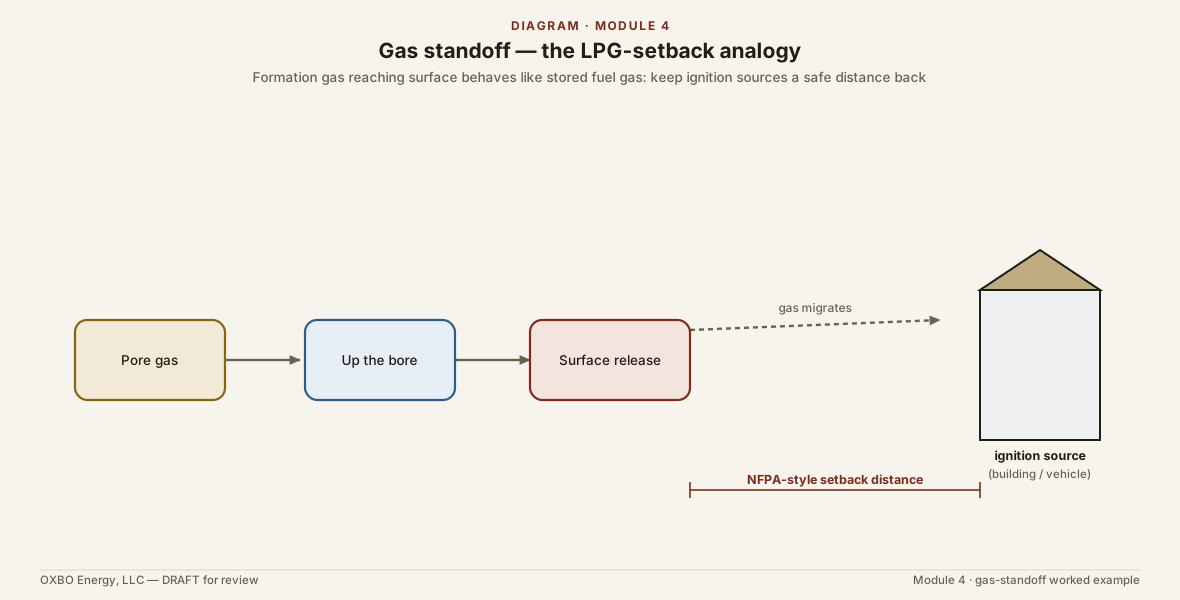
The distances above measure a site against water, mines, and intakes, but a gas-prone bore also stands at some distance from the buildings around it, and that distance belongs in the assessment for the same reason the others do. Module 3 traced how shallow gas that escapes a bore can migrate laterally through permeable ground and along utility corridors and collect in a structure well away from the hole, and how the heavier gases pool in the basements, vaults, trenches, and below-grade parking where people are least likely to expect them. The Oakville and Hutchinson cases of Module 0 are that pathway realized. What the area assessment lacks is a way to size the standoff that a gas-prone bore should keep from an occupied building, because no standard sets one for a geoexchange bore.
One way to size it is to treat the worst plausible gas pocket as a buried store of flammable gas and to borrow the separation distance that the liquefied-petroleum-gas code already assigns to a store of that size. The reasoning runs in four steps, and its conclusion turns out to be stable enough that the exact inputs matter little.
The first step is the pocket itself. A reasonable worst case for a shallow biogenic accumulation, a buried swamp or drift-gas lens of the kind Module 3 described, is one acre-foot of gas-charged sediment at ten percent porosity. That is a gas-filled pore volume of
of gas held at formation pressure.
The second step expands that gas to the pressure at which it threatens a building. Gas that migrates up to a foundation or a below-grade space arrives at close to atmospheric pressure, so the formation volume is expanded by Boyle’s law,
where the formation pressure is the hydrostatic pressure at the depth of the pocket. For a deep modern bore near 1,600 ft, the formation pressure is on the order of 735 psia, an expansion of roughly fifty to one, so the gas cloud delivered to the surface is on the order of
The third step converts that cloud to an equivalent liquefied-petroleum-gas container. One gallon of liquid propane releases about 36.4 ft³ of vapor, and a container is filled to about eighty percent of its water capacity, so a cloud of 218,000 ft³ corresponds to roughly 6,000 gallons of liquid, held in a container of about
The fourth step reads the separation the code assigns to a container of that size. OSHA’s liquefied-petroleum-gas standard, 29 CFR 1910.110, Table H-23, adopting NFPA 58, sets the minimum distance from a container of 2,001 to 30,000 gallons water capacity to an important building, or to the line of adjoining property that may be built upon, at fifty feet, and in that size band the distance for an underground container is also fifty feet, so burying the store does not reduce it. A 7,500-gallon container falls in that band, which places the standoff at fifty feet.
The conclusion is steadier than any single input to it. The fifty-foot band covers every equivalent container from 2,001 to 30,000 gallons, and on the reasoning above a one-acre-foot pocket reaches the bottom of that band at a depth near 400 ft and does not leave the top of it until a depth well past 6,000 ft, deeper than this work goes. The equivalent container therefore stays in the fifty-foot band across the whole range of geoexchange and water-well depth, so the standoff does not depend on knowing the depth of the pocket or on pricing the analogy precisely.
| Depth of pocket | Formation pressure | Expansion | Equivalent container | Code standoff |
|---|---|---|---|---|
| 500 ft | 231 psia | 16x | ~2,350 gal | 50 ft |
| 1,000 ft | 448 psia | 30x | ~4,560 gal | 50 ft |
| 1,600 ft | 735 psia | 50x | ~7,500 gal | 50 ft |
| 2,000 ft | 881 psia | 60x | ~8,960 gal | 50 ft |
Below roughly 400 to 500 ft the equivalent container falls into the 501-to-2,000-gallon band, for which the code distance is twenty-five feet, so the reasoning yields a smaller standoff for the shallowest bores rather than none.
Two limits keep this in proportion. The liquefied-petroleum-gas distances were written for a stored and possibly leaking tank, with its fire and dispersion behavior, rather than for a formation, so the fifty feet is a reasoned default borrowed from a comparable stored-gas hazard, not a code requirement that governs a geoexchange bore. And where the authority having jurisdiction sets its own setback from buildings or property lines, that setback governs, and the desk study records it in place of this one. The standoff is measured to the nearest important building and to the below-grade and enclosed spaces near it, because, as Module 3 set out, those are the spaces a migrating gas reaches and fills.
4.8 Planning the Mitigation
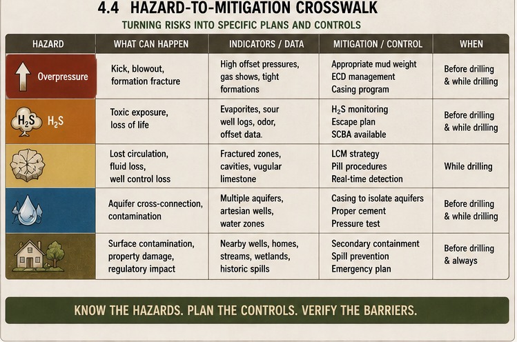
Identification is the first half of the desk study. The second plans the mitigation for each hazard the assessment raised, so that the equipment, the monitoring, and the response are specified before the rig arrives. The desk study specifies what a site requires. The active control of a flowing bore, the operation of a barrier, and the methods of a kill are the subject of Module 6, and the detection of an influx at the rig is the subject of Module 5. What follows is the plan, not the execution.
| Identified hazard | Potential mitigation(s) |
|---|---|
| Artesian or high-head zone | Flow-diversion and control equipment; a plan that does not rely on shutting in; casing set to isolate the head |
| Kick-prone or over-pressured zone | A casing program with defined setpoints; a diverter or, for the higher-risk site, a blowout preventer; a fluid program that holds the window |
| Flammable gas (methane) | Continuous gas monitoring; ignition-source control; diversion of returns away from the crew |
| Hydrogen sulfide | Continuous H₂S monitoring; respiratory protection; a hydrogen-sulfide contingency in the emergency-response plan (ANSI/ASSP Z390.1) |
| Asphyxiant or toxic gas (carbon dioxide) | Atmospheric monitoring; ventilation; confined-space and below-grade controls |
| Radioactive ground (radon, NORM) | Radon and radiation monitoring where the section warrants it; exposure controls scaled to the project’s duration |
| Contaminant plume or prohibition zone | A siting check against the remediation record; casing and zonal isolation to prevent cross-connection; relocation where a zone bars the site |
| Brine or multi-aquifer section | A zonal isolation material matched to the chemistry; baseline groundwater sampling before construction |
| Faults, fractures, or karst; mine voids | Casing and zonal isolation across the conduit; a lost-circulation plan; gas monitoring where a void or mine is near |
| Seismic hazard | Casing and isolation designed for the ground motion; attention to the long-term integrity of the seal (Module 7) |
| Gas-prone site with an occupied building inside the standoff | Increase the standoff or relocate the bore; where it cannot be met, gas monitoring at the structure, ignition-source and below-grade-space controls, and the authority’s own setback confirmed (Section 4.7.1) |
| Any credible influx | Baseline groundwater sampling; an emergency-response plan; verified insurance; confirmation of the authority’s requirements |
The intensity of the plan follows the hazards found. A site with a shallow, quiet, single freshwater aquifer and no gassy, sour, or contaminated ground warrants little beyond good construction practice. A site with a sour zone, an artesian head, a nearby mine, or a legacy field near a contaminant plume warrants the full set. The desk study is where that judgment is made and written down.
4.9 Air Drilling and the Diverter
Air and other gaseous drilling fluids are common in geoexchange and water-well work, and they change the barrier picture enough to warrant their own place in the risk assessment. Air drilling carries no column of fluid in the hole, so it holds nothing back against a pressured zone. Its safety rests on the ground being competent and dry and on a diverter at surface, and both must be examined rather than assumed, which makes air drilling an added risk factor in its own right.
A diverter is not a primary barrier. It becomes one only when the casing it is mounted on is cemented and pressure tested, because only a cemented and tested string can be trusted to contain pressure and to anchor what sits on top of it. Mounted on an uncemented conduit, the diverter is bolted to a string the ground has not yet secured.
What a diverter actually provides is time. It routes an influx away from the rig floor and the crew, extending the interval in which people can react and the well can be addressed. It is a response-time extender, not a shut-in device, and it is not complete on its own. A working diverter system includes a mud/gas separator to handle the returns and a flare to burn the diverted gas at a safe distance. Without them, the diverter relocates the hazard rather than controlling it.
A diverter that can be fully closed is more dangerous than one that cannot. Closing a diverter on an uncemented conduit lets pressure build against a string the ground has not anchored, and under high pressure the conduit itself can be driven out of the earth like a projectile, carrying the diverter with it. A diverter is meant to stay open to the separator and the flare, diverting flow rather than closing on it.
The assumption that makes air drilling defensible is that it becomes impractical the moment a layer flows liquid, because the air can no longer lift the returns. A driller who reasonably anticipated a liquid influx would not be air drilling in the first place. That is what the desk study establishes. Where the prognosis and the fluid assessment flag a pressured or flowing zone, air drilling is not the right method, and the plan calls for a fluid column and a cemented, tested barrier instead. Air drilling is defensible only where the desk study shows the ground dry and competent to the planned depth.
4.10 The Authority Having Jurisdiction
The desk study asks the authority having jurisdiction what it requires before, during, and after construction, because those requirements set the floor for the job. The questions cover the permit and its conditions, the construction and sealing standards, the rules for a flowing or artesian well, the setback and prohibition zones, and the reporting required for an encounter. The answers vary widely. Module 3 noted that some jurisdictions already require much of this, as British Columbia’s Groundwater Protection Regulation requires flowing-artesian wells to be controlled and their shut-in pressure reported, and Ontario’s Wells Regulation requires cased and sealed wells and the prevention of movement of water between aquifers. Where the authority requires little, the desk study is what supplies the missing plan.
4.11 The Emergency-Response Plan
The desk study requires an emergency-response plan scaled to the identified hazards and confirms one exists before the job begins. The plan builds on the employer’s emergency action plan (OSHA 29 CFR 1910.38) and, where a hazardous atmosphere or substance is credible, on the hazardous-waste-operations and emergency-response rule (29 CFR 1910.120), and for hydrogen sulfide it follows the accepted training and contingency practice of ANSI/ASSP Z390.1. The plan names the hazards, the monitoring, the muster and evacuation, the protective equipment, and the notifications, and where a release could reach navigable water it names the federal reporting the area assessment flagged. A plan prepared before the job is what carries a recognized influx through to a controlled one.
4.12 Insurance
Insurance for the well-control peril is the most poorly understood part of the risk, and the desk study is where a responsible party confirms what coverage is in force and, in many cases, learns that the most expensive part of the peril is not covered at all. What follows names the common policies, what they cover, what they exclude, and the specialty product built for this exposure. It is general information for planning, not legal or insurance advice, and coverage turns on the exact policy wording and the jurisdiction.
A commercial general liability policy is the coverage most contractors carry, and it does real work here, though not the work most people assume. Its purpose is to answer third-party claims, meaning money owed to someone else for harm the work caused, and a loss of control can produce exactly those: a neighbor’s home explosion from migrating methane, a hydrogen-sulfide injury to a passerby, damage to adjoining property. For those claims the general liability policy is the primary line, subject to its exclusions. What it does not do is pay the insured’s own first-party cost of regaining control of a flowing bore and redrilling it. That cost is not a third-party claim for property damage, and it is further barred by the owned-property and business-risk exclusions, so it falls outside the policy on more than one ground. The pollution of an aquifer or a surface water is commonly removed by the policy’s pollution exclusion as well, which is the specific gap that pollution coverage is written to fill.
A separate pollution or environmental policy addresses that gap. Contractors pollution liability and sudden-and-accidental pollution coverage are written for water-well and geothermal drilling programs, and they can respond to third-party aquifer or surface-water contamination and its cleanup arising from a sudden release, including one driven by a loss of control, subject to their own exclusions. What they do not fund is the loss of well control itself and the cost of a redrill.
Every liability policy is also subject to a further principle, that insurance is meant for losses that are accidental and unexpected rather than ones the insured could foresee. A genuine influx that takes the crew by surprise is the kind of sudden event insurance exists for. The harder case is a bore deliberately advanced into a pressured or hazardous zone that was known, or that a reasonable study would have revealed. The Fifth Circuit addressed the first version of that case in Meridian Oil Production, Inc. v. Hartford Accident & Indemnity Co., 27 F.3d 150 (5th Cir. 1994), holding, under Texas law and on facts where the operator had actual knowledge of the geology and prior regulatory warnings, that pollution which predictably followed from its deliberate drilling was not a covered “occurrence.” An insurer may try to extend that reasoning to a driller who skipped an available study, arguing the driller should be treated as knowing what the study would have shown. That argument asks a court to blur the negligence question of what a driller should have known with the narrower coverage question of what the insured actually knew or expected, and whether it succeeds is unsettled and depends on the jurisdiction. Ordinary negligence, including a failure to investigate, is usually still an insurable accident.
The coverage built specifically for the first-party peril is control-of-well insurance, known in the specialty market as operators extra expense (OEE), which funds the regaining of control, the redrill, and the seepage and pollution that follow a loss of control. It is an oil-and-gas line, written for the party holding the operating interest and keyed to that party’s own well, so a contract geoexchange or water-well driller is usually neither its natural buyer nor an automatic insured under anyone else’s OEE. For most of the work this course addresses, that means the first-party cost of killing a flowing bore and redrilling it is effectively uninsured, whatever third-party coverage may exist.
Risk is also allocated by contract, and here the oil-and-gas world has a statutory backstop that this sector lacks. The oilfield anti-indemnity acts of Texas (Tex. Civ. Prac. & Rem. Code ch. 127), Louisiana (La. R.S. 9:2780; Meloy v. Conoco, Inc., 504 So.2d 833 (La. 1987)), New Mexico (N.M. Stat. § 56-7-2), and Wyoming (Wyo. Stat. § 30-1-131) void an agreement that indemnifies a party against its own negligence in a well contract, which protects the smaller contractor from a one-sided hold-harmless clause. By their terms these acts reach contracts for oil, gas, mineral, and water wells, so a conventional water-well contract in those states may fall under them, though the acts are not absolute and generally permit indemnity supported by separately purchased insurance. Whether they extend to a sealed, closed-loop geoexchange bore, which produces and disposes of nothing, is a separate and likely negative question. Where no such statute applies, a driller can be bound by a broad indemnity clause that obligates it to absorb another party’s negligence, an uninsured contractual exposure that counsel should review before signing.
The practical result is a stack rather than a single policy. General liability answers third-party injury and damage, contractors pollution liability answers a contamination event, and careful contract terms allocate fault, while the first-party cost of regaining control and redrilling is left largely uninsured unless an operator-style control-of-well line is in place. The party who drills without the study, without that specialty coverage, and without a favorable contract holds that first-party exposure alone. The Kerrisdale flow of Module 3, which reached eight figures, shows the scale a single bore can reach.
4.13 Synthesis: The One-Page Pre-Drilling Risk Sheet
The desk study resolves to a single page, backed by its two tables and its cross-section. The sheet below is the summary a crew carries to the site and an engineer or authority signs.
| Pre-Drilling Risk Sheet | Entry |
|---|---|
| Site and bore | Location, coordinates, planned depth and diameter, purpose |
| Sources assessed | Geological survey; oil-gas-mineral; injection; water-well; abandoned mine; solid waste; environmental remediation; the authority (Desk-Study Directory) |
| Geologic prognosis | Attached: formation tops, water salinity and oil fraction, gas presence flags, pore and fracture pressure gradients, other hazards |
| Offset wells and cross-section | Attached: offsets by direction and distance; legacy and abandoned wells treated as suspected conduits |
| Area assessment | Class V and VI wells and landfills within 5 miles; gas, H₂S, and brine in water wells within 1 mile; artesian flow; faults, fractures, or karst; contamination or prohibition zone; distances to navigable water, fresh water, public intake, and mines; seismic hazard |
| Building proximity | Distance to the nearest important building and to below-grade spaces; the standoff of Section 4.7.1 met, or the authority’s setback applied, or the deviation recorded |
| Risk level | Low, elevated, or high, from the hazards found |
| Planned mitigation | The potential mitigation(s) for each hazard (Section 4.8) |
| Authority requirements | Permit conditions; construction, sealing, flowing-well, setback, and reporting rules |
| Insurance | General and pollution liability; control-of-well (OEE) coverage verified, or its absence recorded (Section 4.12) |
| Emergency-response plan | In place, scaled to the hazards; H₂S and spill-reporting contingencies where warranted |
| Sign-off | Engineer, authority, and driller, each to their share |
The Desk Study as the Standard of Care
The desk study discharges the identification duty in full, and it is more than good practice. The law measures a professional against what a reasonable practitioner in the same position knew or should have known, and the desk study is what a reasonable one would have done. A bore advanced into a pressured, gassy, or contaminated zone that the public record would have revealed is not excused by a crew that did not look, because the standard is the knowledge a reasonable study would have produced. A crew that drills deep without the study accepts the exposure that skipping it creates.
Who holds that exposure depends on the work. A water-well driller drills until the hole makes water, so he owns the depth and the method, and the identification duty and its risk fall to him. An engineered geoexchange system divides the roles. An engineer of record specifies the depth and the design and answers to the owner, so the duty to know what that depth penetrates is first the engineer’s, carried on a professional line of insurance, while the driller holds the recognition of the hazard at the rig. Where an engineer of record exists, the desk study is his standard of care. Where none does, as on most water-well and small residential work, the duty collapses onto the driller by default.
As Section 4.12 set out, the oil-and-gas tools for shifting this risk, the specialty coverage and the anti-indemnity statutes, do not reach residential geoexchange. What governs instead is ordinary negligence, the non-delegable duty owed for inherently dangerous work, and in some courts a strict liability for abnormally dangerous activity, and a homeowner’s insurer that pays a loss will pursue the driller for it. The classification the introduction described fixes the construction standard the driller is held to, and because that classification is unsettled across the states, so is the standard the same work is measured against.
What the desk study cannot do is make its own use mandatory. It is performed where a responsible party chooses to perform it, and it is skipped where none does. The bore-construction standard the course calls for is the instrument that would require this page, assign its parts to the engineer of record, the authority, and the driller, and make the identification a condition of the work rather than a matter argued after a loss. This section is general information, not legal advice, and the outcome of any case turns on its jurisdiction and its facts.
Module Boundaries
- Modules 1 through 3 supply what the desk study assesses: the pressures that pre-exist, the pressures the operation induces, and the fluids an influx delivers.
- Module 5 examines the detection of an influx at the rig, the layer that catches what the assessment missed.
- Module 6 examines the barriers and the active control of a flowing bore, the execution of the equipment this module specifies.
- Module 7 examines the zonal isolation that this module calls for and that must hold over the operating life of the asset.
- Module 8 examines the records that carry the risk forward, including the baseline sampling this module requires and the reporting of any encounter.
The desk study ends before the rig starts, and it hands the crew a page that says what the ground may hold and how the job is prepared to meet it. Module 5 turns to the rig, where the influx the assessment anticipated, or the one it missed, first appears.
Key References
- American National Standards Institute / American Society of Safety Professionals. ANSI/ASSP Z390.1, Accepted Practices for Hydrogen Sulfide (H₂S) Training Programs (2024).
- International Risk Management Institute (IRMI). Operators Extra Expense (OEE) and The CGL Pollution Exclusion.
- Insurance and liability (general information, not legal advice): Meridian Oil Production, Inc. v. Hartford Accident & Indemnity Co., 27 F.3d 150 (5th Cir. 1994) (pollution predictably resulting from deliberate drilling is not a covered “occurrence”; the fortuity requirement); the oilfield anti-indemnity acts — Texas (Tex. Civ. Prac. & Rem. Code ch. 127), Louisiana (La. R.S. 9:2780; Meloy v. Conoco, Inc., 504 So.2d 833 (La. 1987)), New Mexico (N.M. Stat. § 56-7-2), and Wyoming (Wyo. Stat. § 30-1-131), each of which by its terms reaches oil, gas, mineral, and water wells and each of which permits indemnity supported by separately purchased insurance (the Louisiana Marcel exception; the Texas mutual-indemnity safe harbor, § 127.005); Restatement (Second) of Torts §§ 519–520 (abnormally dangerous activity) and §§ 416, 427 (non-delegable duty); the survey of well-blowout coverage disputes in the Oil & Gas Journal (CGL owned-property, care-custody-and-control, pollution, and well-control exclusions), and contractors pollution liability as the pollution-coverage line for water-well and geothermal programs; GeoExchange Organization, on the classification of closed-loop geothermal boreholes among the states.
- Occupational Safety and Health Administration (OSHA). 29 CFR 1910.38 (emergency action plans); 29 CFR 1910.120 (hazardous waste operations and emergency response).
- Occupational Safety and Health Administration (OSHA). 29 CFR 1910.110, Storage and Handling of Liquefied Petroleum Gases, Table H-23 (container separation distances), adopting NFPA 58, Liquefied Petroleum Gas Code — borrowed in Section 4.7.1 as a reasoned analogy for a building standoff from a gas-prone bore.
- U.S. Environmental Protection Agency. Underground Injection Control program, well Class V (shallow and geothermal injection) and Class VI (geologic sequestration of carbon dioxide); Superfund and contaminated-site records; Clean Water Act navigable-waters and spill-reporting requirements (40 CFR 112), including the Spill Prevention, Control, and Countermeasure requirements for onshore oil drilling and workover facilities (40 CFR 112.10).
- U.S. Geological Survey. National Seismic Hazard Model and seismic-hazard tools; and, with the American Society of Civil Engineers, the ASCE 7 Seismic Design Categories.
- Government of Ontario. Wells Regulation (O. Reg. 903 under the Ontario Water Resources Act): construction, casing, annular sealing, flowing-well control, and prevention of movement of water between aquifers.
- Province of British Columbia. Groundwater Protection Regulation under the Water Sustainability Act (2016): flowing-artesian well control, construction and sealing standards, and certified well drillers.
- U.S. Office of Surface Mining Reclamation and Enforcement (abandoned-mine inventory); state geological surveys and environmental-remediation programs — record sources indexed in the Desk-Study Directory.
- Legacy and orphaned wells (on the well-control relevance of a well’s status record): National Academies of Sciences, Engineering, and Medicine, Practices and Standards for Plugging Orphaned and Abandoned Hydrocarbon Wells: Proceedings of a Workshop (2024); and reporting on Texas orphaned and “zombie” wells returning to pressure despite plugged-status records (Texas Tribune, 2025; Insurance Journal, 2024), including field documentation by Sarah Stogner and Hawk Dunlap.
- OXBO Energy. Desk-Study Directory (companion to Module 4): state geological, oil-gas-mineral, injection, water-well, abandoned-mine, solid-waste, and environmental-remediation portals, with a Module 1 mechanism crosswalk and federal resources.
Appendix A — The Desk-Study Directory: Public Source Crosswalk
This appendix reproduces the Desk-Study Directory, the companion crosswalk introduced in Section 4.2. For every pressure source and sink of Module 1, it names the official government portal where a driller, engineer, or regulator can research it, state by state, so that the records the desk study draws on can be reached directly rather than searched for. It has three parts: a crosswalk from each Module 1 mechanism to the record that reveals it, the national portals that apply everywhere, and the state-by-state directory of the six core record types.
The directory was compiled and machine-checked for this first version, in July 2026. Most links resolved to the correct official agency, a minority were blocked by automated checks and are given as the parent agency page or marked accordingly, and “limited/none” marks a state with no meaningful program of that type, such as no oil-and-gas regulator or no coal abandoned-mine program. The agency name is the durable key, because a web address changes while the agency endures, and every link is confirmed before it is relied on. Injection-well oversight is split between the states that hold primacy and the ones the U.S. EPA regional office runs directly, and the UIC column notes which. This version covers the U.S. states; the Canadian provinces relevant to the incident record, Ontario and British Columbia, are a planned addition.
A.1 Module 1 Pressure Mechanism to Record Crosswalk
| Pressure mechanism (Module 1) | What to look for | Federal resource | State column to use |
|---|---|---|---|
| Compaction / undercompaction & lithostatic (matrix failure) | Overpressure trend with depth; thick young/undercompacted sections; overburden gradient | USGS NGMDB; state basin studies | Geological Survey |
| Gas generation — biogenic / drift gas | Organic-rich shallow units, peat, black shale, valley-fill methane | USGS methane-in-groundwater studies | Geological Survey; Water-Well/Groundwater |
| Uplift, erosion & subnormal pressure | Unconformities; uplifted/eroded terrain; relaxed/depleted zones | USGS NGMDB | Geological Survey |
| Tectonic stress, faults & earthquakes | Mapped faults, horst/graben blocks, seismicity | USGS Quaternary Fault DB; Earthquake Hazards | Geological Survey |
| Confined aquifers / artesian (elevated recharge) | Potentiometric surface; flowing-well areas; confining beds | USGS NWIS | Water-Well/Groundwater |
| Salt / evaporite / karst (seal & dissolution) | Salt & gypsum bodies; karst voids; dissolution/collapse | USGS Karst Aquifers | Geological Survey |
| Injection wells (induced pressure) | Nearby Class I/II injection & disposal wells | EPA UIC | UIC Program |
| Underground gas storage | Storage fields; seasonal re-pressurization | PHMSA / EIA | Oil&Gas/Well DB |
| Depletion (subnormal / thief zones) | Depleted oil & gas reservoirs | State O&G well DB | Oil&Gas/Well DB |
| Legacy & orphan wells (pathways/sources) | Abandoned/undocumented wells within search radius | USGS Orphaned Wells | Oil&Gas/Well DB |
| Abandoned mines (voids, flooded head, combustion) | Mine maps, workings, AML sites; mine-fire history | OSMRE e-AMLIS | Abandoned Mine/AML |
| Landfills (gas + leachate) | Active & closed dumps, quarry/pit fill; landfill gas | EPA LMOP | Solid Waste/Landfill |
| Buried valleys | Buried bedrock valleys; confined gravel/drift aquifers | USGS / state drift mapping | Geological Survey |
A.2 Federal Resources (National Portals)
| Topic | Resource |
|---|---|
| Geology & maps | USGS National Geologic Map Database |
| Groundwater data | USGS National Water Information System (NWIS) |
| Groundwater primer | USGS Basic Ground-Water Hydrology (Heath, WSP 2220) |
| Faults & seismicity | USGS Quaternary Fault & Fold Database |
| Earthquakes | USGS Earthquake Hazards Program |
| Karst / sinkholes | USGS Karst Aquifers |
| Orphan / legacy wells | USGS Orphaned Wells program |
| Injection wells | US EPA Underground Injection Control (UIC) |
| Abandoned mines | OSMRE e-AMLIS (Abandoned Mine Land Inventory) |
| Mine reclamation / mine fires | OSMRE Abandoned Mine Land Program |
| Underground gas storage | PHMSA Underground Natural Gas Storage |
| Gas storage basics | US EIA Underground Natural Gas Storage Basics |
| Landfill gas | US EPA Landfill Methane Outreach Program (LMOP) |
| Landfill gas health | ATSDR Landfill Gas Primer |
A.3 State Directory: 50 States, Six Core Record Portals
Each cell links to the agency portal for that record type. Where a state has no meaningful program of a type, the cell reads “limited/none.”
Appendix B — Offset Cross-Section (Worked Example)
The cross-section is the second product of Section 4.5, the offset wells projected onto a section through the planned bore with their formation tops correlated by surface elevation. The example below was built from public offset-well logs using an offset-well analysis tool. Figure B.1 shows the offset selection and the interpolated stratigraphic column for the site; Figure B.2 resolves that column to the engineering properties, fluids, risk gases, and pore pressure the desk study reads, with the base of fresh water marked.
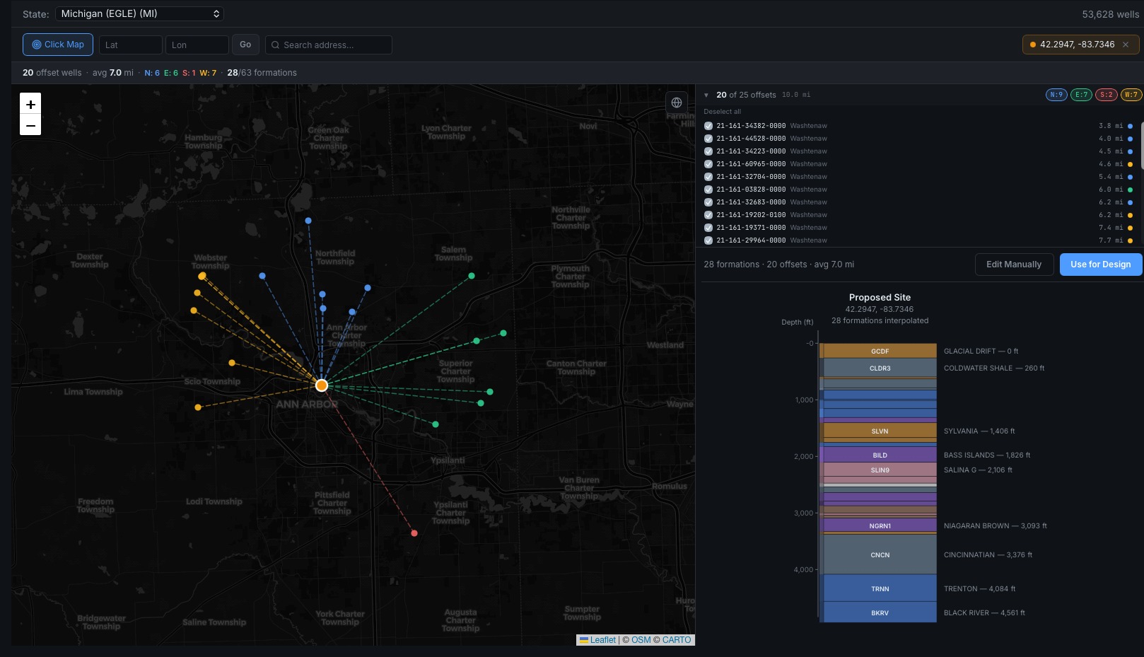
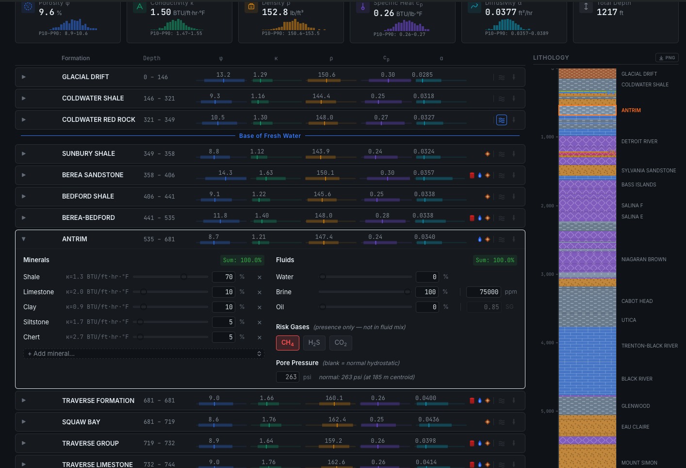
Figure B.1 — Offset-well selection and interpolated column for a proposed site near Ann Arbor, Michigan. Figure B.2 — the same column resolved to formation properties, fluids, risk gases, and pore pressure (both rendered in the HTML edition). Courtesy OXBO Energy Rok.
This module is © 2026 Nathan Zenero, OXBO Energy, LLC and is licensed under the Creative Commons Attribution-NonCommercial 4.0 International license (CC BY-NC 4.0), on the terms stated in Module 0. Requests for commercial licensing, submissions for the public errata, and accounts of encountered influx may be sent to nathan@oxbo.energy.