
Author: Nathan Zenero, OXBO Energy, LLC
Audience. Written for working geoexchange and water-well drillers and their crews, and for the contractors, design engineers, specifiers, and regulatory authorities who share responsibility for the boreholes they construct.
Pressure Generated by the Operation
Module 1 established that any subsurface pressure identifiable before spudding is created by a physical mechanism, stored behind a geological seal, and accessed along a hydraulic pathway. The pre-drilling desk study is the instrument for anticipating it. This module addresses a second class of pressure, one that originates in the drilling operation and does not exist in the formation before the rig arrives. It is generated by the movement of the drill string, the circulation of the drilling fluid, and the chemical and mechanical disturbance the borehole imposes on the surrounding rock. Because this pressure has no pre-drilling existence, no desk study can forecast it, and its only control is operational practice.
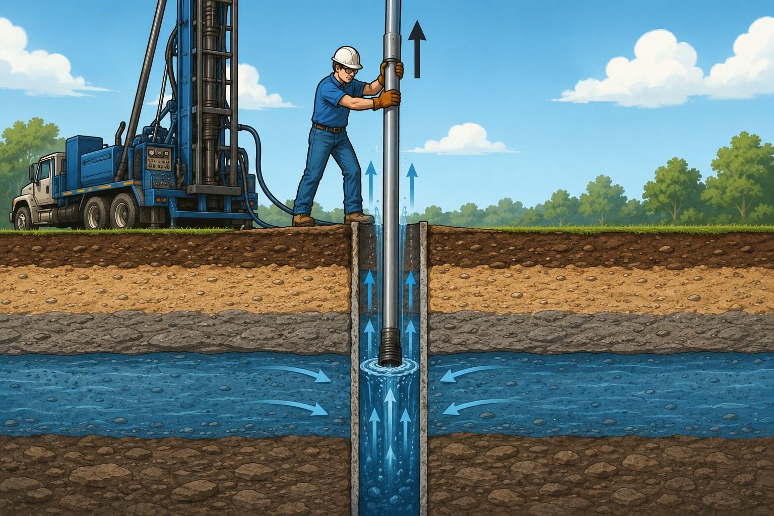
The source-and-sink framework of Module 1 continues to apply, because an operationally induced pressure can drive fluid across the borehole wall in either direction. When the operation raises the wellbore pressure above the formation pressure, it drives fluid into the rock and can fracture it, producing lost circulation into an operationally created sink. When it lowers the wellbore pressure below the pore pressure, it draws formation fluid into the borehole, producing an influx from an operationally created source.
In geoexchange and water-well bores, the drilling fluid is usually unweighted water or a light bentonite or polymer system, and the margin between pore pressure and the fracture gradient can be narrow. Where it is, a small induced change can cross a bound that a wider margin would absorb, because the fluid column carries little reserve in either direction.
A Note on Shared Responsibility
The identification duty defined in Module 1 is shared and clear: the engineer and the authority having jurisdiction lead the desk study, and the driller recognizes pressure at the rig. The operational duty of this module is not. In mineral-well drilling, an engineer specifies the fluid program, the casing points, and the tripping and flow-check standards, and a regulator verifies them. Geoexchange and water-well work has no such specifications, so this duty is undefined, and Section 2.7 returns to the gap. Because the desk study cannot help once the bit is turning, prevention rests on execution at the rig, on every trip, connection, and loop insertion.
Module Structure
- Section 2.1 defines operationally induced pressure and distinguishes it from the pre-drilling pressure of Module 1.
- Section 2.2 sets out the operating pressure window, its pore-pressure and fracture-pressure bounds, and the Equivalent Circulating Density that moves between them.
- Section 2.3 examines pressure induced by axial movement of pipe, casing, and the ground loop, together with hole fill, grouting, and the filter cake.
- Section 2.4 addresses the elevated exposure to a loss of control during tripping, casing running, and loop installation.
- Section 2.5 examines pressure induced by circulation and by restriction of the annular return path.
- Section 2.6 covers pressure and stress induced by chemical and mechanical alteration of the formation.
- Section 2.7 consolidates the prevention matrix, the undefined operational duty, and the boundaries with adjacent modules.
2.1 Operationally Induced Pressure: Definition and Scope
Operationally induced pressure is any deviation from the static wellbore pressure that the operation produces rather than the undisturbed formation. It falls into two categories. The first is a transient change in the effective pressure of the fluid column, produced by moving the string or circulating the fluid. The second is a change in the mechanical or chemical state of the rock, produced by the borehole’s disturbance of it. Both are absent from the undisturbed formation and appear only while the operation proceeds.
Identified versus Generated Pressure
| Attribute | Identified (Module 1) | Generated (Module 2) |
|---|---|---|
| Origin | Pre-exists in the formation | Created by rig action and fluid dynamics |
| Storage | Trapped behind a geological seal | Dynamic; exists only during operations |
| Control | Pre-drilling desk study | Real-time tripping, circulating, and fluid practice |
The dividing line is predictable-in-advance versus created-in-the-moment, not natural versus induced: the pre-existing anthropogenic pressures a desk study can find remain within Module 1.
The Governing Relation
Module 1 expressed the static column pressure as:
with in lb/gal and in feet. During operations, the pressure the formation actually experiences is this static value modified by an induced term:
The induced term is positive during surge, circulation, and pack-off, and negative during swab or a falling fluid level. Its magnitude, rather than the static mud weight alone, decides whether the wellbore fractures the formation or admits an influx.
2.2 The Operating Pressure Window
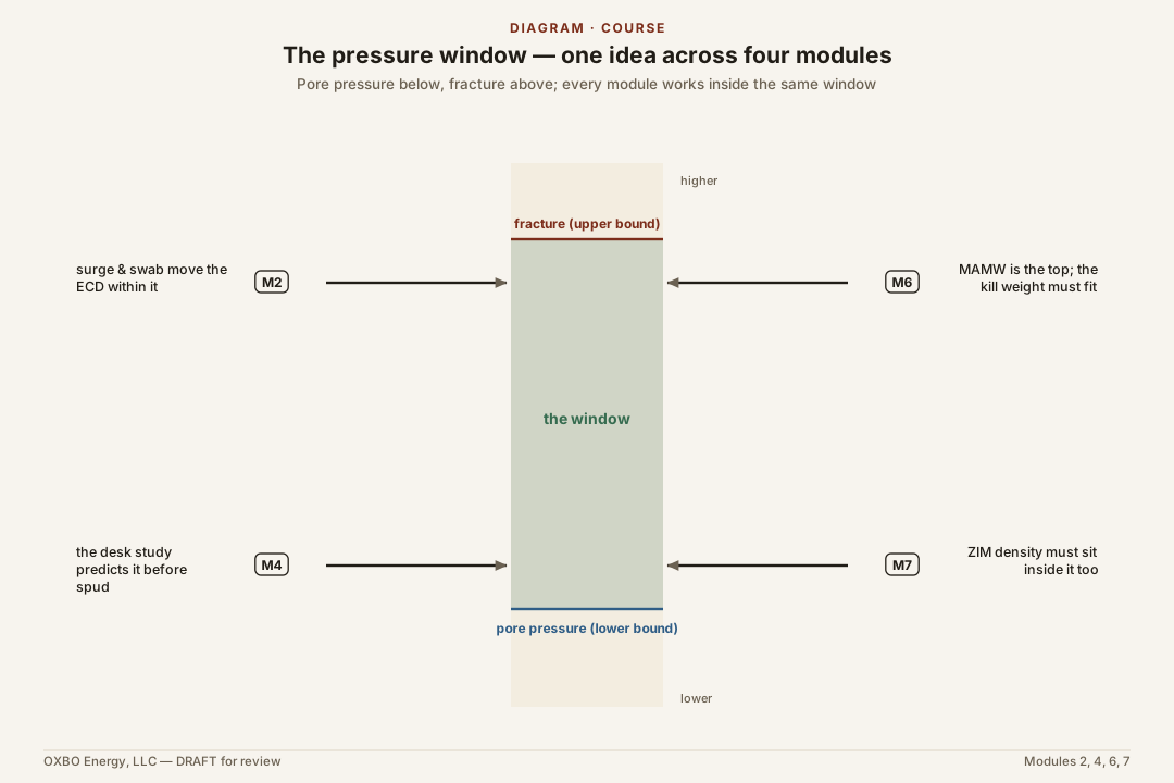
Every operationally induced pressure acts upon a single quantity: the pressure the drilling fluid exerts against the formation at the borehole wall. That pressure is bounded by two properties of the rock. The treatment here is conceptual, because estimating the bounds from offset logs is a geophysical task the course does not ask of the driller. The aim is to show how the quantities interact (Espinoza, The Mud Window).
- Pore pressure () is the fluid pressure in the connected pore space, and the lower bound of the window. If , formation fluid enters the borehole. Swab lowers the wellbore pressure toward this bound.
- Fracture pressure () is the pressure at which the wall parts and takes fluid, and the upper bound. If , lost circulation follows. Surge, circulating friction, and pack-off raise the wellbore pressure toward this bound. A fracture, once opened, does not reliably reseal.
The interval between the two bounds is the operating window, and the wellbore pressure must remain within it throughout the operation. In weighted-fluid drilling the window is wide. In the light-fluid geoexchange and water-well bore it is narrow, because the rock is weak and the fluid carries little reserve above the pore pressure. A narrow window turns a small induced change into a crossed bound.
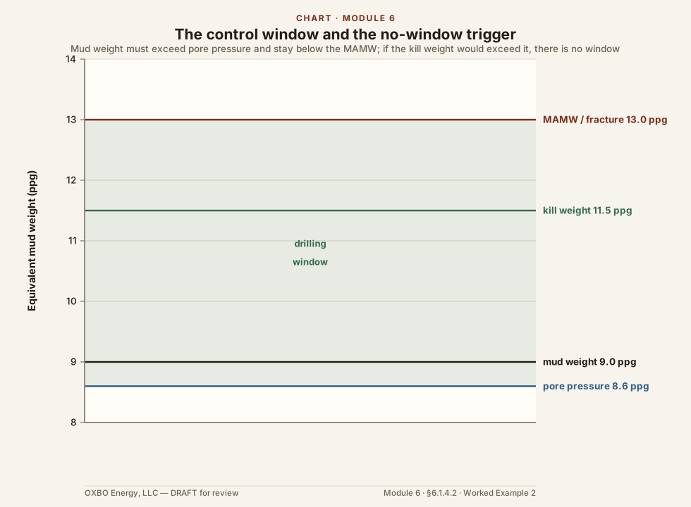
Mud Weight as a Two-Sided Lever
Mud weight sets the static base within the window. Set too low, it lets a minor swab drop the wellbore below the pore pressure. Set too high, it lets routine circulation carry the wellbore above the fracture pressure. The mud weight is chosen to place the static pressure within the window with margin on both sides, rather than to maximize overbalance. The practical ceiling is the leak-off pressure (), the pressure at which fluid begins entering the rock before a gross fracture opens, measured by a leak-off or formation-integrity test.
Equivalent Circulating Density
The pressure the formation feels is not the static mud weight alone. It is the sum of the static hydrostatic pressure and every induced component acting at that moment. Expressed as a fluid density, that total is the Equivalent Circulating Density:
where is the annular friction pressure. Surge adds to it and swab subtracts from it, so the Equivalent Circulating Density, rather than the static mud weight, is the quantity that must remain inside the window (API RP 13D).
Three Operational States
- Underbalanced (): the wellbore is underbalanced and formation fluid enters as a kick.
- Overbalanced (): the wellbore is controlled. A small filtrate seepage into permeable rock is limited by the filter cake described in Section 2.3, and this controlled seepage is the normal condition of overbalanced drilling.
- Above the fracture bound (): the formation fractures and takes fluid into an induced fracture. Because a large loss lowers the fluid column and its hydrostatic pressure, a fracture can bring the wellbore below the pore pressure elsewhere in the hole, so a loss at the upper bound can become an influx at the lower one — the most severe of the three states.
The mechanisms in the rest of the module are the operational means by which the Equivalent Circulating Density is driven across a bound, together with the practice that keeps it inside.
2.3 Pressure Induced by Axial Movement: Surge and Swab
Moving pipe, casing, or the ground loop through a fluid-filled borehole displaces fluid and generates a transient pressure set by the displacement and the annular clearance (Burkhardt, 1961). Running the string down raises the bottomhole pressure toward the fracture bound, a positive transient termed surge. Withdrawing it lowers the pressure toward the pore-pressure bound, a negative transient termed swab.
Piston Displacement and Annular Amplification
A body run down the hole acts as a loose piston, forcing the displaced fluid up the annulus. By continuity, the annular velocity is amplified over the running speed:
where is the body’s cross-section and the open annular area.
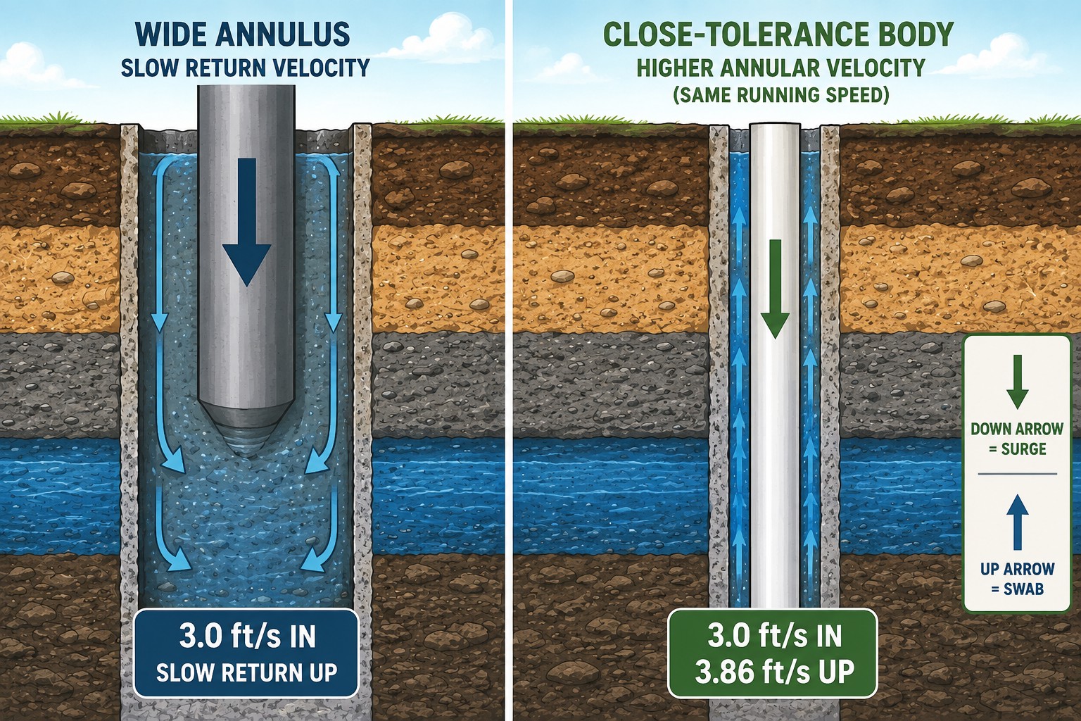
For a PVC casing run into a hole at :
A run of drives up the annulus, and the boundary layer of fluid dragged along the moving body raises the effective velocity further. Surge and swab therefore rise with running speed, with fluid viscosity and gel strength, with the length of string already in the hole, and as the annular clearance narrows.
Surge
Running down raises the bottomhole pressure. Where surge carries the Equivalent Circulating Density above the fracture pressure, the exposed formation fractures and takes fluid. The condition is worst with a close-tolerance casing or screen, with a closed lower end — a cap or a plugged bit displaces the full body rather than the annular cross-section — and with a rapid run into a tight annulus. Detection of the resulting loss is the subject of Module 5.
Swab
Pulling up lowers the bottomhole pressure behind the ascending string, and where the reduction brings the wellbore below the pore pressure, the formation delivers an influx. Consider an bore drilled on water over a formation whose pore pressure is . The static bottomhole pressure is:
A rapid pull that generates a swab lowers the effective pressure:
The well passes from static to flowing on the pull alone. Gas drawn in this way returns to surface as trip or connection gas, an influx indicator handled in Module 5.
Fluid Height and Hole Fill
Swab is the dynamic part of the pressure loss on a trip. A second, static loss occurs whenever pipe, casing, or loop is withdrawn without replacing its volume: the fluid level falls by the volume removed, and the hydrostatic pressure falls with it at every depth below. The practice that prevents it is to keep the hole full, adding fluid as the string or loop comes out. The magnitude is not trivial. On the same water, a drop in level removes:
lowering the bottomhole pressure to , a underbalance on the same formation. This loss is independent of swab and adds to it on a trip out. A hole that takes less fluid than the volume of pipe or loop removed is not staying full, which is an early indication of an influx and the reason the fill volume is reconciled against the volume removed on the trip sheet (Module 5). The case recurs during loop installation, where a loop that buckles, sticks, or falls short of bottom is withdrawn and re-run, each pull removing its volume again.
Filter Cake and the Surge–Swab Tradeoff
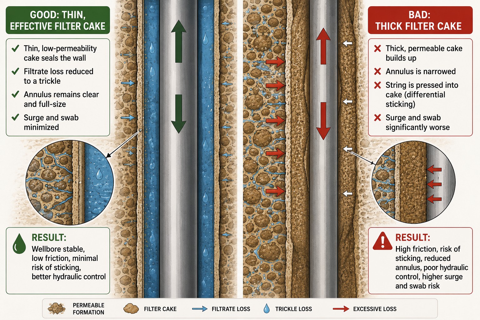
The overbalanced condition of Section 2.2 is held without continuous loss by the filter cake, a thin layer of drilling-fluid solids deposited on the wall of a permeable formation. As filtrate is driven into the rock, the suspended solids are strained out at the wall and build a low-permeability cake that seals the formation and reduces the loss to a small rate after the brief initial spurt loss (API RP 13B-1). The cake carries an opposing consequence, because it occupies part of the annular clearance: a thick cake narrows the annulus, raises the surge and swab produced by a given running speed, and can hold the moving string against a permeable wall as differential-pressure sticking. The cake must therefore be low in permeability yet thin, which is a matter of fluid design.
Casing, Screen, and Loop Running
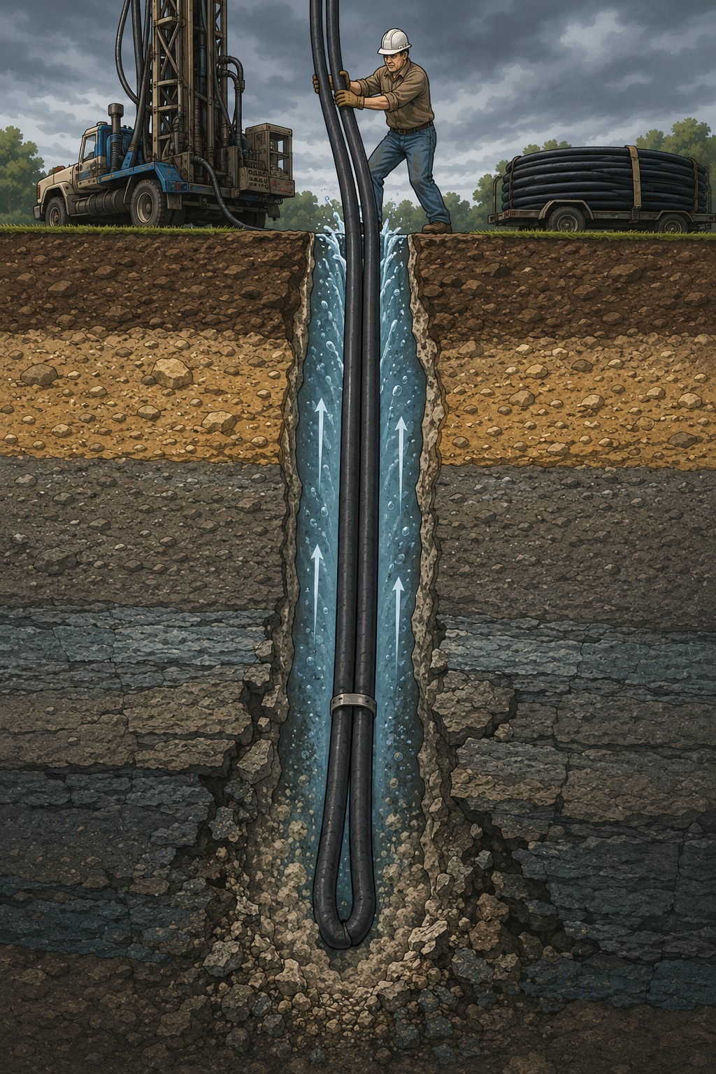
Running casing or screen, commonly PVC in this work, generates a larger surge than running drill pipe at the same speed, because the casing has a larger diameter and a smaller annular clearance and is often closed at the lower end. The controlling practices are a reduced running speed and, where the design permits, filling the casing from the top. The HDPE ground loop is the case distinctive to geoexchange: a light but close-tolerance body that must be pushed against its own buoyancy into a static, uncased, and often unmonitored open hole, surging a weak formation at the least-watched moment of the operation. Controlled insertion speed and a hole conditioned and stable before insertion govern it.
Pressure Induced by Grouting
Grouting imposes a pressure of its own, because the grout fills the borehole as a fluid column whose hydrostatic pressure is set by its density and height. Geothermal grouts run heavier than the fluid they displace, from a high-solids bentonite near to a cement of or more, so the grout column can exceed the fracture pressure and fracture the rock during placement. The friction of pumping the grout, treated with the other circulating friction in Section 2.5, adds to it.
A second pressure appears as the grout sets. While the grout is fluid it transmits its full hydrostatic pressure to the formation, but as it gels and stiffens toward a set it transmits less, and the pressure it holds against the formation falls. Where that pressure falls below the pore pressure, formation fluid or gas can invade the setting grout and migrate upward, in some cases carrying grout back to the surface — a discharge drillers call spitting — hours or days after placement. The author has seen boreholes discharge grout more than a day after the tremie job. The mechanism is the gas migration known from well cementing, in which the setting cement loses the ability to transmit hydrostatic pressure and formation gas invades once that pressure drops below the pore pressure (Nelson and Guillot, 2006). Grout also bleeds, settles, and shrinks as it cures, so the top of the column subsides and must be topped off. A column left short exerts less pressure over the zones below it and leaves a gap in the seal it was placed to form.
Each of these is a well control event that occurs during or after completion, when the rig may already have moved off, and the prevailing standards do not verify grouting as a pressure barrier. The ASHRAE Handbook chapter on ground-source heat pumps and the IGSHPA Design and Installation Standards specify the grout’s thermal conductivity and permeability, but in the editions reviewed neither requires the grout density as pumped to be recorded, the top of grout to be documented, or a margin above the pore pressure to be held. Some state codes, among them Tennessee and Michigan, require the density and the topping-off of subsidence, yet none set a pressure margin above the pore pressure. The grout is specified as a thermal and contaminant seal rather than a pressure barrier, so whether a given column holds back formation pressure is not established by the standards that govern its placement. Readers aware of such a requirement are invited to submit it for the errata. The verification of grout as a permanent barrier belongs to Module 7. The concern here is the pressure the operation induces during and after placement.
Prevention
The surge and swab transients are governed by the speed of movement and the condition of the fluid. Controlled running and pulling speeds limit the induced annular velocity, slow and staged breaking of circulation limits the pressure needed to restore flow, and conditioning the fluid to a thin, competent cake and a moderate gel strength reduces both the friction and the sticking. The flow check performed after a trip confirms that the wellbore is static, and its procedure is detailed in Module 5.
2.4 Operational Exposure: The Trip and Casing Run
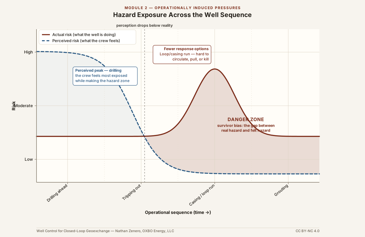
The mechanisms of Section 2.3 do not distribute their hazard evenly across the operation. The swab transient arises only on withdrawal, and its consequence is greatest during the trip out and during the running of casing or the ground loop. The well control record bears this out: a large share of influxes, and a disproportionate share of the most severe events, are taken when the crew is not drilling ahead.
Four Compounding Factors
- The operation generates the influx. While drilling ahead the wellbore penetrates a pressure that already exists. On a trip the swab transient lowers the bottomhole pressure and draws the influx in, so the crew causes the kick by the act of pulling.
- Detection degrades once the pumps stop. The flow and pit indicators that reveal a gain while circulating are unavailable, and detection falls to reconciling the fill volume against the volume removed on the trip sheet, which lags a circulating gain.
- Control is diminished. With the bit off bottom or out of the hole, a conventional circulate-out is unavailable, and the crew may have to strip back in against pressure with the influx already rising in the annulus.
- The barrier is being removed. Casing and loop runs are close-tolerance and worsen the swab, and a displacement to a lighter fluid pulls the primary barrier while attention is on the running operation.
The Record
The Deepwater Horizon blowout at the Macondo well in 2010 occurred during temporary abandonment, as the crew displaced the drilling mud with seawater after the casing had been cemented and a series of negative-pressure tests had been misread, well after drilling had ended (National Academies, 2012). The influx entered and rose while the primary barrier was being removed and the monitoring that would have caught it was misjudged. The same pattern appears in this work: the Fulton County, Ohio bore of 2026, recorded in Module 0, met gas during construction rather than during a monitored advance of the bit. That investigation is open, so the course notes the incident as consistent with the pattern rather than a confirmed instance. Geoexchange bores are not exempt, because the loop is run and grouted at the end of the sequence, in the very mode the record marks as most dangerous.
Human Factors
The physics and the psychology of the trip act together. When a crew drills through a known or suspected hazard zone without incident, the perceived risk declines, and the vigilance it warranted relaxes just as the trip out re-exposes the crew to that zone through swab. Two established effects describe the decline. Under risk compensation, also termed risk homeostasis, people accept greater exposure as a hazard appears to recede (Wilde, 1982). Under normalization of deviance, a departure from the standard that has been tolerated without consequence becomes the routine (Vaughan, 1996). Both are central to the human-factors analyses of the Macondo blowout. Fatigue compounds them, because the operations that carry the greatest exposure are also the most strenuous, and wrestling a stiff, buoyant HDPE loop or a casing string at the end of a shift erodes vigilance exactly when the hole must be kept full and the flow check performed. The most dangerous influx is frequently the one taken after the zone has been drilled.
The Case for a Written Standard
A written standard is the strongest defense in this window, because it removes the decision from a crew whose vigilance is eroding. Where a standard sets the tripping and insertion speeds and requires a flow check to be performed and recorded, correct practice no longer depends on the crew’s judgment of residual risk in the moment. This work seldom has such a standard, so that judgment rests on the crew at the point of greatest exposure, and Section 2.7 returns to the standard it calls for.
2.5 Circulation and Restricted Annular Flow
Equivalent Circulating Density Under Flow
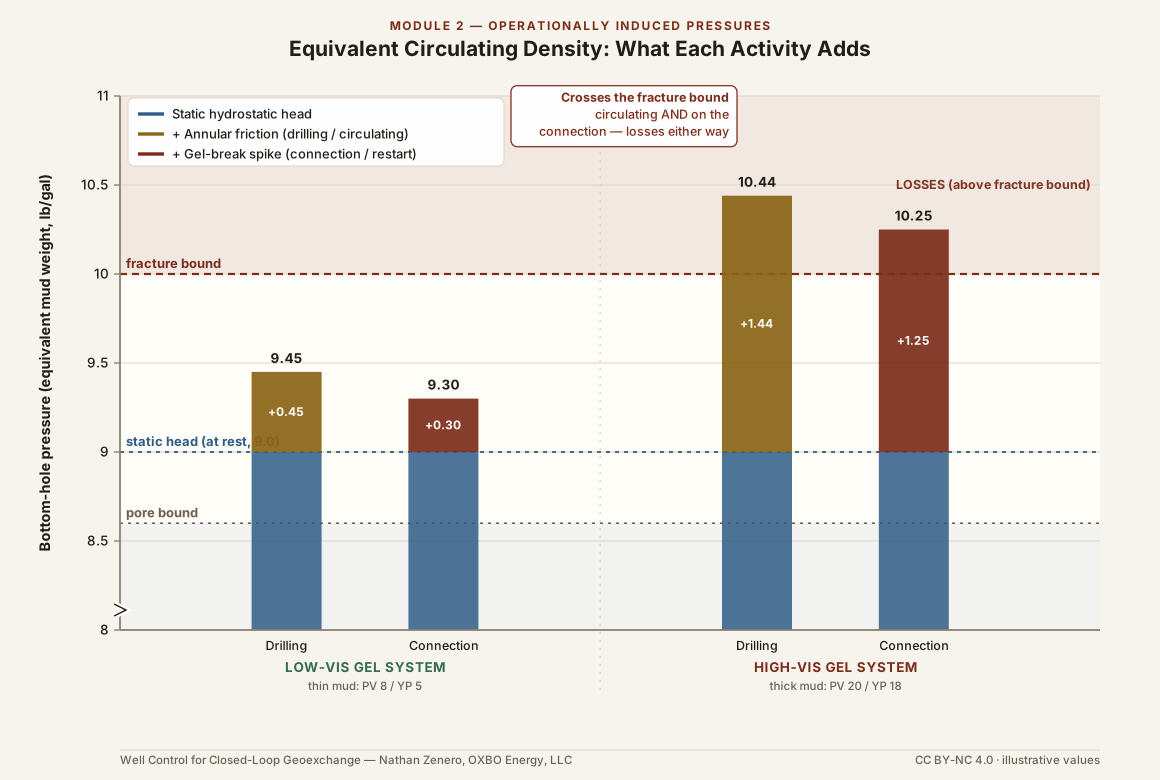
Circulating the fluid adds an annular friction pressure to the static column and raises the pressure the formation experiences. Consider an bore on mud in which circulation develops a annular friction pressure:
Against a fracture gradient equivalent to (), the well is stable while static but fractures the moment the pump starts, because a fluid weight safe at rest can cross the fracture bound once it is circulated. Detection of the loss is Module 5, and its control is Module 6.
Friction, Rate, and Viscosity
The annular friction pressure is not fixed. It rises with the pump rate, with the fluid’s viscosity, and with any narrowing of the flow path (API RP 13D). Those who grout through coiled tubing see the effect directly, because pumping a viscous grout through a small-diameter string raises the treating pressure at the pump well above that of a large-bore tremie, and the same friction reaches the formation at depth. During drilling, an uncontrolled rise in viscosity, from contamination, over-treatment, or accumulated solids, can carry the Equivalent Circulating Density across the fracture bound with no change in pump rate. The same mechanism has a constructive use: in a dynamic kill, a specialist pumps at a high rate so that the sum of the hydrostatic and friction pressures exceeds the formation pressure and arrests a flowing well, supplying through friction the pressure the static column cannot (Grace, 2003). The design of a kill belongs to Module 6. The friction component of the Equivalent Circulating Density is a real and controllable pressure, dangerous when it is left unmanaged and useful when it is applied on purpose.
Breaking Circulation
A drilling fluid left static develops gel strength, and restoring flow requires the pump to shear that gel throughout the annulus, which produces a pressure peak above the steady circulating value. Started abruptly, the peak adds to the bottomhole pressure and can fracture a marginal formation at the instant flow resumes. Circulation is therefore broken slowly and in stages, especially after a loop has stood in a fluid-filled hole.
Formation Compressibility and the Elastic Limit
The rock around the borehole and the fluid-filled hole are not perfectly rigid. Under an increase in pressure the near-wellbore rock compresses and the borehole dilates slightly, so the hole accepts a small additional volume of fluid without any being lost to a fracture or to the formation’s permeability, and when the pressure falls the rock relaxes and returns that volume. The response is elastic, and therefore reversible, so long as the pressure stays within the rock’s elastic limit. Beyond that limit the rock no longer recovers: in tension the wall fractures, the fracture pressure of Section 2.2 is reached, and the fluid driven into the formation is lost rather than stored. The difference between elastic storage below the limit and fracture above it is the difference between the reversible wellbore breathing described next and the irreversible loss of a fractured formation (Espinoza).
Wellbore Breathing
Wellbore breathing, or ballooning, is this elastic storage seen at the flow check. As the circulating pressure approaches the fracture gradient, the near-wellbore rock accepts fluid into elastic deformation and narrow fractures while the pump runs, and returns it when the pump stops and the pressure falls, so the wellbore appears to take fluid during circulation and deliver it at the check. The hazard is misdiagnosis in either direction: treating a true influx as breathing delays the response to a genuine event, while treating breathing as an influx triggers an unnecessary shut-in. The distinction is one of volume. A returned volume equal to the volume lost, and then stopping, is breathing. A returned volume that exceeds the loss and continues to build is an influx. Its reconciliation is detailed in Module 5.

Fluid Density and Solids Control
The condition of the drilling fluid is a pressure in its own right. Drilled solids are meant to be removed at surface before the fluid returns to the hole (API RP 13C), and where solids control is inadequate and they accumulate, two properties of the fluid rise together: its density, which raises the static hydrostatic pressure, and its viscosity, which raises the annular friction pressure. Both lift the Equivalent Circulating Density, and they compound, because a solids-laden fluid is at once heavier and more viscous and drives the wellbore toward the fracture bound from two directions at once. The consequences run past lost circulation. The thickened fluid cleans the hole poorly and forms the cuttings beds that bridge the annulus, its solids degrade the filter cake and worsen the differential sticking of Section 2.3, and a string that is seized and cannot be freed is a string of tools lost in the hole. The maintenance of fluid density and the removal of drilled solids are therefore matters of well control, not of drilling efficiency alone.
Pack-Off and Bridge Overpressure
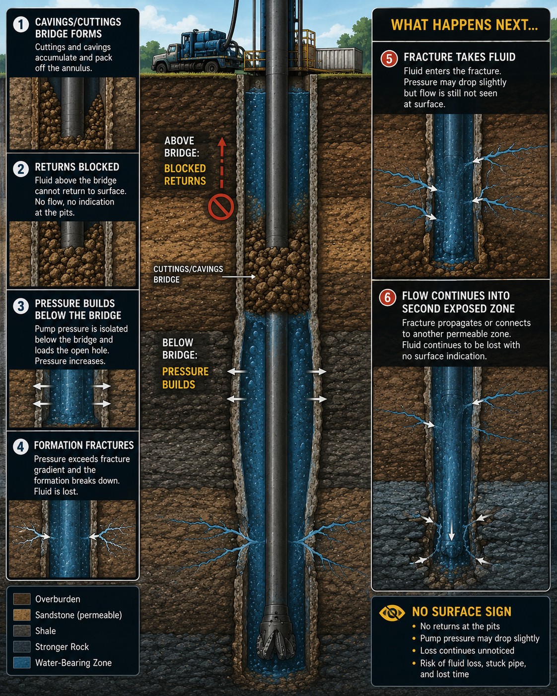
When cuttings accumulate, the wall sloughs, or a swelling formation closes on the string, the annulus can bridge or pack off and restrict the return flow. With the annulus blocked, continued pumping is no longer relieved to surface, and the pump loads the open hole below the restriction. Consider a bridge at in a hole on mud, where the static hydrostatic pressure below the bridge is:
If the crew pumps on and the pump pressure rises before flow is stopped, the interval below the bridge experiences . Against a fracture pressure of (a gradient at ), the formation fractures and takes the pumped fluid, and where two zones are exposed below the bridge it can drive an underground flow between them with no sign at the surface. The rising pump pressure against a restriction is the warning, so the response is to reduce the rate and investigate rather than to pump harder.
2.6 Chemical and Mechanical Formation Alteration
The borehole alters the rock it penetrates. Where the drilling fluid meets reactive minerals, or where the removal of rock redistributes the local stress, the formation generates a pressure or stress against the wall, governed by fluid selection and drilling practice rather than by the desk study. Module 1 flags the presence of the reactive rock. This section examines the reaction it induces.
Chemical Alteration
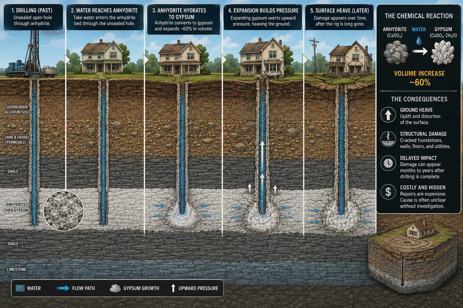
- Anhydrite hydration (): anhydrite contacted by fresh water hydrates to gypsum, a reaction that increases the mineral volume by up to (Sass and Burbaum, 2010) and exerts a swelling pressure against the wall, the casing, and the grout, heaving the overlying ground as it did at Staufen, Germany, in 2007.
- Evaporite dissolution: fresh fluid circulated against halite or gypsum dissolves the mineral, enlarging the borehole, raising the local fluid density, and degrading the seal that Module 7 depends on.
- Fluid–formation incompatibility: a fluid mismatched to the formation, such as fresh water on a water-sensitive shale, triggers the mechanical reactions below, and a compatible fluid is the control.
Mechanical Alteration
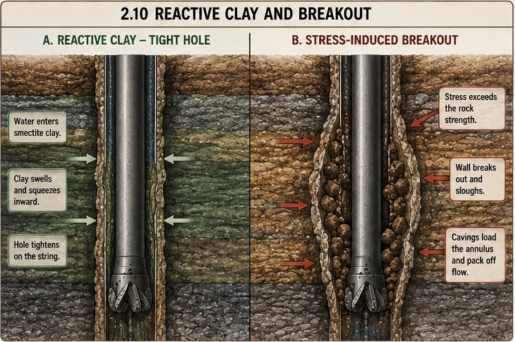
- Reactive and swelling clays: water-sensitive shales and clays that contain smectite absorb filtrate, swell into the borehole, and close on the string, which makes swelling clay a principal cause of the tight hole and pack-off of Section 2.5 (van Oort, 2003). Inhibitive fluid and a limited exposure time are the controls.
- Wellbore instability and breakout: removing rock to drill the hole concentrates the in-situ stress at the wall, and where the concentrated stress exceeds the rock’s strength the wall sloughs, enlarging the hole and loading the annulus with cavings. This gives the window a geomechanical lower bound, the collapse pressure, that can sit above the pore pressure. In the overbalanced water-based bore the controlling bounds remain pore and fracture pressure, and the collapse pressure is the stress-driven mechanism behind the tight hole and the cavings.
The identification of the stuck pipe, tight hole, and loss that follow from these mechanisms belongs to Module 5. This section treats only the induced mechanism that generates the stress.
Prevention
An inhibitive and compatible fluid matched to the reactive lithologies identified in the Module 4 desk study limits both the chemical reactions and the swelling of clays, effective hole cleaning removes the cavings that bridge the annulus, and a limited open-hole exposure time shortens the interval a reactive or unstable formation stands open before it is cased, grouted, or fitted with the loop.
2.7 Synthesis: Prevention, Duty, and Boundaries
Because these pressures cannot be forecast, their control is entirely preventive. The matrix below consolidates each mechanism, its physical process, its manifestation at the rig floor, and the practice that governs it.
| Induced Mechanism | Physical Process | Rig-Floor Sign | Governing Prevention |
|---|---|---|---|
| Surge | Displacement ahead of a descending string raises pressure toward the fracture bound. | Losses while running pipe, casing, or loop. | Controlled run speed; annular clearance; thin cake. |
| Swab | Reversed displacement lowers pressure toward the pore bound. | Influx, trip or connection gas after a pull. | Controlled pull speed; flow check and trip sheet. |
| Loss of fluid height | Withdrawing volume without replacement lowers the head. | Hole takes less fluid than the volume removed; falling level. | Keep the hole full; reconcile the trip sheet. |
| Grouting | The grout column can fracture; setting grout loses head and admits fluid; the column subsides. | Lost grout; grout spitting after placement; subsidence. | Density and column control; monitor and top off; verify (M7). |
| ECD and friction | Annular friction, rising with rate and viscosity, adds to the head. | Losses that start and stop with the pump. | Rate and rheology control; solids removal. |
| Drilled solids | Solids raise density and viscosity together. | High pressures; tight hole; differential sticking; lost tools. | Solids-control equipment; density maintenance. |
| Breaking circulation | Gel strength shears at a pressure peak. | Spike and losses on resuming circulation. | Slow, staged start; gel control. |
| Wellbore breathing | Elastic storage returns fluid reversibly. | Flow-check return equal to the volume lost. | ECD below the fracture bound; volume reconciliation. |
| Pack-off and bridge | A blocked annulus loads the open hole below. | Rising pump pressure with lost returns. | Hole cleaning; reduce rate and investigate. |
| Chemical alteration | Hydration or dissolution swells or voids the rock. | Heave; washouts; tight spots. | Compatible, inhibitive fluid; zonal isolation. |
| Mechanical alteration | Swelling or stress closes or enlarges the hole. | Torque, drag, pack-off, cavings. | Inhibitive fluid; hole cleaning; short exposure. |
The Undefined Duty and a Missing Standard
The identification duty of Module 1 is shared and clear. The operational duty of this module is not. In mineral-well drilling an engineer specifies the fluid program, the casing points, and the tripping and flow-check standards, and a regulator verifies them, so the duty is defined and assigned. Geoexchange and water-well work has no such definition — no engineered fluid program, no tripping or flow-check standard, and no verifying authority — so the duty is assigned to no one and falls by default to the driller, a burden the mineral-well driller does not carry alone. An undefined duty is a well control risk, and defining it lies beyond any single crew. A drilling and bore-construction standard for this work, one that specifies the fluid program, the tripping and insertion practice, the flow check, and the grouting and its verification, would define the duty and assign it across the engineer, the authority, and the driller. This course identifies the gap and calls for that standard, in the interest of protecting life, health, property, and the environment.
Module Boundaries
- Module 3 examines the formation fluids that an induced influx delivers, and their hazards to health, safety, property, and the environment.
- Module 5 examines the detection of an induced influx or loss, through surge, swab, ballooning, lost circulation, and pack-off, by means of the flow check and the trip sheet.
- Module 6 examines the selection and deployment of barriers, and the kill, once an influx has occurred.
- Module 7 examines the zonal isolation that must withstand the pressures imposed over the operating life of the asset, including thermal loading and the verification of the grout column as a permanent barrier.
Prevention keeps the Equivalent Circulating Density inside the operating window through the fluid program and the drilling practice. What escapes prevention is detected in Module 5 and controlled in Module 6, and the fluids delivered by any such influx are the subject of Module 3, to which the course now turns.
Key References
- Burkhardt, J.A. (1961). Wellbore Pressure Surges Produced by Pipe Movement. Journal of Petroleum Technology, 13(6), 595–605. (SPE 1546-G).
- Bourgoyne, A.T., Millheim, K.K., Chenevert, M.E., and Young, F.S. (1986). Applied Drilling Engineering. SPE Textbook Series, Vol. 2.
- Espinoza, D.N. Introduction to Energy and Geomechanics (open-access text on rock elasticity and mud-window mechanics). https://dnicolasespinoza.github.io/
- American Petroleum Institute. API RP 13D (Rheology and Hydraulics), API RP 13B-1 (Field Testing Water-based Fluids), API RP 13C (Solids Processing).
- Grace, R.D. (2003). Blowout and Well Control Handbook. Gulf Professional Publishing.
- Nelson, E.B., and Guillot, D. (eds.) (2006). Well Cementing (2nd ed.). Schlumberger.
- van Oort, E. (2003). On the physical and chemical stability of shales. Journal of Petroleum Science and Engineering, 38(3–4), 213–235.
- Sass, I., and Burbaum, U. (2010). Damage to the historic town of Staufen (Germany) caused by geothermal drillings through anhydrite-bearing formations. Acta Carsologica, 39(2).
- National Academies of Sciences, Engineering, and Medicine (2012). Macondo Well Deepwater Horizon Blowout: Lessons for Improving Offshore Drilling Safety.
- Wilde, G.J.S. (1982). The Theory of Risk Homeostasis. Risk Analysis, 2(4), 209–225.
- Vaughan, D. (1996). The Challenger Launch Decision: Risky Technology, Culture, and Deviance at NASA. University of Chicago Press.
- IGSHPA (2017). Closed-Loop/Geothermal Heat Pump Systems Design and Installation Standards. Oklahoma State University.
- ASHRAE (2023). Handbook — HVAC Applications, Chapter 35: Ground-Source Heat Pumps and Geothermal Energy.
This module is © 2026 Nathan Zenero, OXBO Energy, LLC and is licensed under the Creative Commons Attribution-NonCommercial 4.0 International license (CC BY-NC 4.0), on the terms stated in Module 0. Requests for commercial licensing, submissions for the public errata, and accounts of encountered influx may be sent to nathan@oxbo.energy.